Chapter 9
Page no. 1132
JC-DR-A-190.fm
GE Healthcare
Senographe DS
Revision 1
Service Information and Procedures Class A 2385072-16-8EN
Job Card D/R A190 - Gantry CPU Board
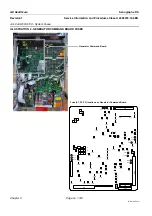
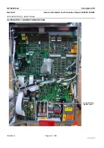
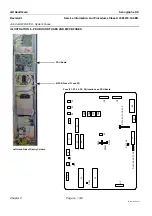
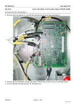
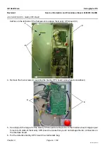
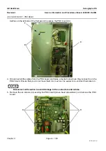
latches on the left side of the framework to expose the Gantry CPU board (3).
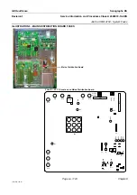
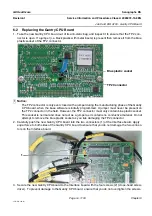
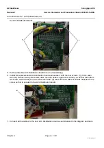
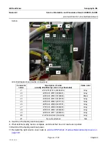
4. Remove the four screws (4) securing the Gantry CPU board (cross-head screwdriver).
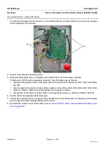
5. Carefully pull the top part of the Gantry CPU board to remove it from the Interface board. Apply equal
force to both sides of the Gantry CPU board to ensure that you do not damage the two connectors on
the Interface board.
6. Put the defective Gantry CPU board in an anti-static bag.
2
3
1
4
4

