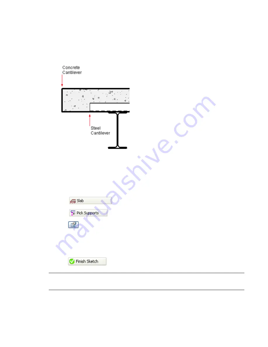
Cantilevers
The Slab Cantilever property allows the sketch of the slab both to be constrained to its supports and its edge
to be extended beyond them. Cantilevers are applied to slabs, either before or after sketching the slab.
Cantilevers are created by adjusting two offset parameters that represent the concrete and steel deck of a
slab.
In composite concrete and metal decks, the steel cantilever parameter will always be the lesser of the two
offsets. In the event that the slab is all concrete or metal, the appropriate offsets should be set.
Applying Cantilevers when Creating a Slab
1
Open a plan view displaying the beams or bay that will support the slab.
2
Select
from the Modelling tab of the Design bar to enter sketch mode.
3
Select
from the Sketch bar.
4
Click
to open the Element Properties dialog.
5
In the Other section, enter offset values for both Concrete Cantilever and Steel Cantilever.
6
Click OK.
7
Select the beams that will support the slab.
8
Click
.
NOTE
The cantilever offset is applied in relation to the direction that the slab edge was created. This is applicable
to line sketching, Pick Supports, or Pick Walls slab creation. In instances where the cantilever appears to be inside
the slab: enter sketch mode, select the edge, and adjust the cantilever values to negative numbers.
Cantilevers | 867
Summary of Contents for 24000-000000-9860 - Revit Architecture - PC
Page 1: ...Revit Architecture 2009 User s Guide April 2008 240A1 050000 PM02A ...
Page 4: ......
Page 56: ...18 ...
Page 116: ...78 Chapter 3 Revit Essentials ...
Page 172: ...134 Chapter 4 ProjectViews ...
Page 178: ...Schedule with Grid Lines Schedule with Grid Lines and an Outline 140 Chapter 4 ProjectViews ...
Page 554: ...516 ...
Page 739: ...Curtain wall Curtain Grid Curtain Walls Curtain Grids and Mullions 701 ...
Page 1004: ...966 ...
Page 1136: ...1098 ...
Page 1226: ...1188 ...
Page 1250: ...1212 ...
Page 1276: ...1238 Chapter 20 Design Options ...
Page 1310: ...1272 ...
Page 1366: ...1328 ...
Page 1406: ...1368 ...


