


EXP-INTF (Expansion Interface Circuit Pack)
Issue 1 May 2002
8-779
555-233-143
If the red LED remains lit, see the previous Note under
Expansion Interface Manual Loop-Back
Procedure
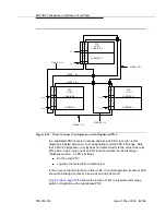
This procedure is to be used when an EI circuit pack cannot be tested by
software. This is usually occurs when the EI circuit pack resides in an
out-of-service PN. When the connection to the EI circuit pack is via fiber, aA short
length of optical fiber is required for this procedure. If a metallic cable is used in
the connection, the metallic connector must be removed from the back of the
carrier, and a lightwave transceiver connected in its place. The short length of
optical fiber can then be used.
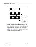
If this procedure is run on both endpoints of a fiber link (EI circuit packs or SNI
circuit packs), and both check out fine, then the failure is most likely in the fiber
itself, assuming neither endpoint circuit pack is busied out and the link remains
inactive.
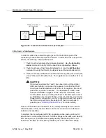
1. Busyout the circuit pack (EI or SNI) using the busyout board UUCSS
command.
2. Disconnect the transmit and receive fiber pair from the lightwave
transceiver behind the circuit pack (EI or SNI) slot.
NOTE:
The fiber connected to the transmit side of the lightwave transceiver
on one EI circuit pack should be connected to the receive side of the
lightwave transceiver on the circuit pack on the opposite end of the
fiber.
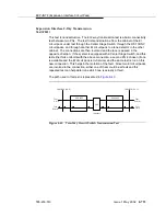
3. Using a fiber jumper cable, interconnect the transmit and receive jacks of
the lightwave transceiver as shown in
.
NOTE:
Make sure that the total length of the fiber jumper cable does not
exceed the maximum length recommended for the fiber link
connections between cabinets. Using cable lengths not within
connectivity guidelines can adversely affect test results.
4. Go to the front of the cabinet and inspect the amber LED.
■
If the amber LED flashes on at a rate of once per second, the (EI or
SNI) circuit pack or transceiver should be replaced.
■
If the amber LED flashes on at a rate of five times per second, the
circuit pack (EI or SNI) or the lightwave transceiver may need
replacement. This condition may also be due to a faulty system
clock on the network containing this EI circuit pack.
■
If the amber LED is not blinking, this circuit pack (EI or SNI) and the
lightwave transceiver are functioning properly.
Содержание S8700 Series
Страница 50: ...Maintenance Architecture 555 233 143 1 26 Issue 1 May 2002 ...
Страница 74: ...Initialization and Recovery 555 233 143 3 12 Issue 1 May 2002 ...
Страница 186: ...Alarms Errors and Troubleshooting 555 233 143 4 112 Issue 1 May 2002 ...
Страница 232: ...Additional Maintenance Procedures 555 233 143 5 46 Issue 1 May 2002 ...
Страница 635: ...status psa Issue 1 May 2002 7 379 555 233 143 status psa See status tti on page 7 406 ...
Страница 722: ...Maintenance Commands 555 233 143 7 466 Issue 1 May 2002 ...
Страница 1121: ...CARR POW Carrier Power Supply Issue 1 May 2002 8 399 555 233 143 Figure 8 19 Power Distribution Unit J58890CH 1 ...
Страница 1447: ...E DIG RES TN800 reserve slot Issue 1 May 2002 8 725 555 233 143 E DIG RES TN800 reserve slot See ASAI RES ...
Страница 1735: ...LGATE AJ Issue 1 May 2002 8 1013 555 233 143 LGATE AJ See BRI SET LGATE BD See BRI BD LGATE PT See BRI PT ...
Страница 1846: ...Maintenance Object Repair Procedures 555 233 143 8 1124 Issue 1 May 2002 Figure 8 62 TN787 MMI MULTIMEDIA INTERFACE CIRCUIT PACK ...