


Maintenance-Object Repair Procedures
555-233-143
8-1444
Issue 1 May 2002
2306
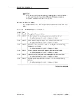
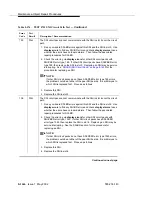
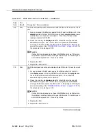
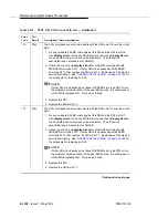
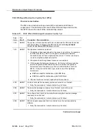
ABORT
The SNI circuit pack is not responding to test requests sent by software.
1. Run the test led switch-node for the switch node where the SNI resides to
verify whether the LEDs on the board light.
2. If the LEDs on the other boards in the carrier light, but the LEDs on this
board do not light, run test 760 via test board UUCSS l for the active SNC
in this carrier. Wait 5 minutes and then try step 1 one more time. If the
LEDs on this board still do not light, replace this board. Replacing an SNI
may be service interrupting. See
‘‘SNI-BD (SNI Circuit Pack)’’ on page
for the procedure for replacing an SNI.
3. If none of the LEDs light for the boards in the same carrier as this board, fix
any problems associated with the connectivity of this carrier to the server.
a. Check list fiber-link to determine the fiber connections to this carrier.
b. Check the LEDs on every SNI and EI, and fix any fiber problems.
c. Enter display errors, and follow the associated repair procedures for
any EXP-INTF error entries associated with the controlling
IPSI-connected EPN.
d. Follow the associated repair procedures for any SYNC, SNI-BD,
SNC-BD, FIBER-LK, or SNI-PEER error entries.
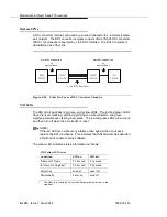
4. Follow the procedure described above, SNI Manual Loopback to determine
whether the circuit pack or the fiber connection is faulty.
102
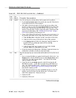
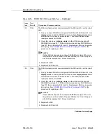
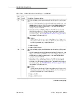
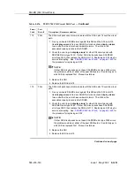
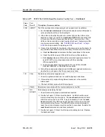
FAIL
The SNI circuit pack cannot communicate with the SNI in slot 2 over the circuit
path.
1. Fix any on-board SNI-BD errors against this SNI and the SNI in slot 2. Use
display errors to find any SNI-BD errors and check display alarms to see
whether the errors have on-board alarms. Then follow the associated
repair procedures for SNI-BD.
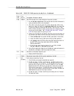
2. Check the error log via display errors for other SNI circuit packs with
SNI-PEER error type 1. If other SNI circuit packs have SNI-PEER error
type 1, then replace the SNI in slot 2. Replacing an SNI may be service
interrupting. See
‘‘SNI-BD (SNI Circuit Pack)’’ on page 8-1429
for the
procedure for replacing an SNI.
3. If other SNI circuit packs do not have SNI-PEER error type 1 errors, the
problem could be at either of the peer SNI boards. It is arbitrary as to
which SNI is replaced first. Proceed as follows:
4. Replace this SNI.
5. Replace the SNI in slot 2.
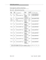
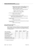
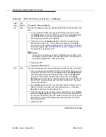
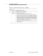
Table 8-576.
TEST #755 SNI Circuit Path Test —
Continued
Error
Code
Test
Result
Description / Recommendation
Continued on next page
Содержание S8700 Series
Страница 50: ...Maintenance Architecture 555 233 143 1 26 Issue 1 May 2002 ...
Страница 74: ...Initialization and Recovery 555 233 143 3 12 Issue 1 May 2002 ...
Страница 186: ...Alarms Errors and Troubleshooting 555 233 143 4 112 Issue 1 May 2002 ...
Страница 232: ...Additional Maintenance Procedures 555 233 143 5 46 Issue 1 May 2002 ...
Страница 635: ...status psa Issue 1 May 2002 7 379 555 233 143 status psa See status tti on page 7 406 ...
Страница 722: ...Maintenance Commands 555 233 143 7 466 Issue 1 May 2002 ...
Страница 1121: ...CARR POW Carrier Power Supply Issue 1 May 2002 8 399 555 233 143 Figure 8 19 Power Distribution Unit J58890CH 1 ...
Страница 1447: ...E DIG RES TN800 reserve slot Issue 1 May 2002 8 725 555 233 143 E DIG RES TN800 reserve slot See ASAI RES ...
Страница 1735: ...LGATE AJ Issue 1 May 2002 8 1013 555 233 143 LGATE AJ See BRI SET LGATE BD See BRI BD LGATE PT See BRI PT ...
Страница 1846: ...Maintenance Object Repair Procedures 555 233 143 8 1124 Issue 1 May 2002 Figure 8 62 TN787 MMI MULTIMEDIA INTERFACE CIRCUIT PACK ...