


change fiber-link
Issue 1 May 2002
7-63
555-233-143
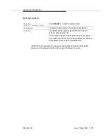
The line equalization setting defaults to the median value of 3. This setting
remains in effect until changed by administration. Incorrect equalizer settings
may cause a higher error rate on the DS1 facility.
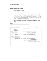
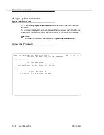
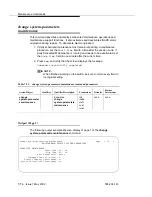
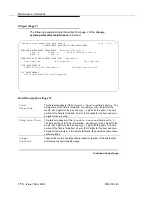
The following display shows a typical result when
change fiber-link 1 is entered
on a high-reliability system (unduplicated PNC and CSS).
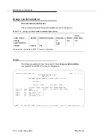
Table 7-9.
DS1 Line Equalization Settings
Equalizer Setting
Distance to DSX-1 Interface (feet)
22 AWG ABAM and 24 AWG PDS
26 AWG PDS
1
1 to 133
0 to 90
2
133 to 266
90 to 180
3
266 to 399
180 to 270
4
399 to 533
270 to 360
5
533 to 655
360 to 450
DS1 CONV-2 Line
Compensation:
Same as the above for ENDPOINT-2 of the DS1 CONV complex.
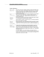
Zero Code
Suppression:
Specifies the line coding format for each facility. Valid entries are: zcs and
b8zs. There are 2 line coding options supported by the DS1 Interfaces to
meet ones-density requirements in the data stream. Zero Code
Suppression (ZCS) line coding is the default and is in place following an
initialization until changed by administration. Note that either line coding
option may be used on the DS1 Interface that carries the packet time slots.
Framing Mode:
Specifies the data framing format (esf or d4) used on the facility. It is
initialized to ESF. In this mode, an automatic selection process is executed
until either the DS1 Interface is brought into frame, or an Options CCMS
message is received by the framing options master. Once options are set by
administration, they remain fixed on the framing option master until the
board is again initialized, reset, or sent new options. The framing option on
the framing option slave converter board can change to track the framing
option master’s option.
Содержание S8700 Series
Страница 50: ...Maintenance Architecture 555 233 143 1 26 Issue 1 May 2002 ...
Страница 74: ...Initialization and Recovery 555 233 143 3 12 Issue 1 May 2002 ...
Страница 186: ...Alarms Errors and Troubleshooting 555 233 143 4 112 Issue 1 May 2002 ...
Страница 232: ...Additional Maintenance Procedures 555 233 143 5 46 Issue 1 May 2002 ...
Страница 635: ...status psa Issue 1 May 2002 7 379 555 233 143 status psa See status tti on page 7 406 ...
Страница 722: ...Maintenance Commands 555 233 143 7 466 Issue 1 May 2002 ...
Страница 1121: ...CARR POW Carrier Power Supply Issue 1 May 2002 8 399 555 233 143 Figure 8 19 Power Distribution Unit J58890CH 1 ...
Страница 1447: ...E DIG RES TN800 reserve slot Issue 1 May 2002 8 725 555 233 143 E DIG RES TN800 reserve slot See ASAI RES ...
Страница 1735: ...LGATE AJ Issue 1 May 2002 8 1013 555 233 143 LGATE AJ See BRI SET LGATE BD See BRI BD LGATE PT See BRI PT ...
Страница 1846: ...Maintenance Object Repair Procedures 555 233 143 8 1124 Issue 1 May 2002 Figure 8 62 TN787 MMI MULTIMEDIA INTERFACE CIRCUIT PACK ...


