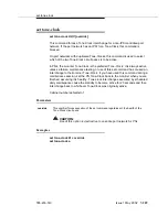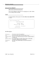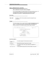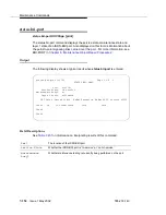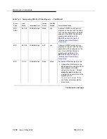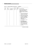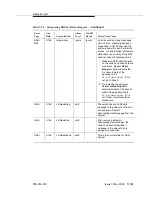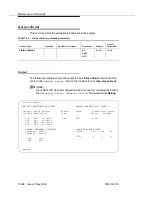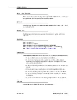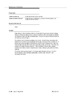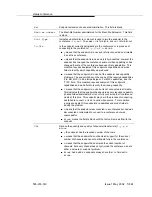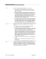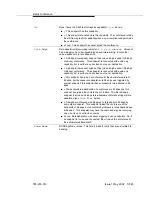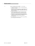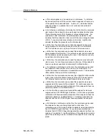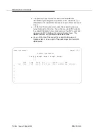
status bri-port
Issue 1 May 2002
7-303
555-233-143
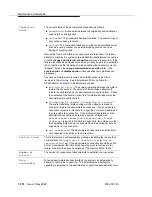
Connectivity
Status
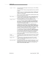
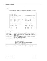
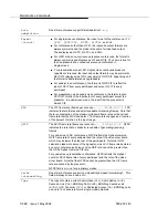
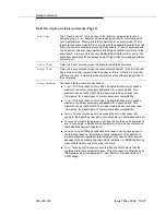
For PNs connectivity status refers to the availability of the EAL (Expansion
Archangel Link) and INL (Indirect Neighbor Link) to the carrier for both
active and standby PNCs (if duplicated). Possible values are:
up — EAL and INL are both available.
down — EAL and INL are both unavailable.
near-end — The EAL is available, and the INL is unavailable.
far-end —The INL is available, and the EAL is unavailable.
blank — In the standby column, this means PNC is not duplicated.
For SNs connectivity status indicates circuit pack insertion on the Switch
Node as follows:
up — At least one switch node interface circuit pack in the Switch Node
is inserted.
down — There are no switch node interface circuit packs inserted on
the Switch Node.
blank — In the active column, this indicates that the Switch Node
carrier is currently the standby in a critical-reliability system. In the
standby column, this indicates that the Switch Node carrier is currently
active (whether or not PNC is duplicated).
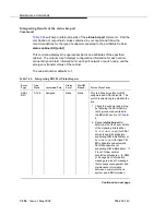
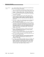
Emergency
Transfer
The location of the circuit pack containing the emergency transfer select
switch (PN maintenance).
Select Switch
The current setting of the emergency transfer switch:
on Emergency transfer has been manually activated.
off Emergency transfer is being manually prevented.
auto+ The cabinet is controlling emergency transfer and it is currently
activated.
auto- The cabinet is controlling emergency transfer it is not currently
activated.
unavail The current setting of the emergency transfer switch is not
available.
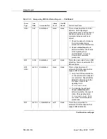
PN/SN
Each Port Network and Switch Node located in the cabinet is identified by
its PN number or its SN number and PNC designation (A or B).
Mj, Mn, Wn
The number of major, minor and warning alarms currently logged against
the Port Network or Switch Node.
Содержание S8700 Series
Страница 50: ...Maintenance Architecture 555 233 143 1 26 Issue 1 May 2002 ...
Страница 74: ...Initialization and Recovery 555 233 143 3 12 Issue 1 May 2002 ...
Страница 186: ...Alarms Errors and Troubleshooting 555 233 143 4 112 Issue 1 May 2002 ...
Страница 232: ...Additional Maintenance Procedures 555 233 143 5 46 Issue 1 May 2002 ...
Страница 635: ...status psa Issue 1 May 2002 7 379 555 233 143 status psa See status tti on page 7 406 ...
Страница 722: ...Maintenance Commands 555 233 143 7 466 Issue 1 May 2002 ...
Страница 1121: ...CARR POW Carrier Power Supply Issue 1 May 2002 8 399 555 233 143 Figure 8 19 Power Distribution Unit J58890CH 1 ...
Страница 1447: ...E DIG RES TN800 reserve slot Issue 1 May 2002 8 725 555 233 143 E DIG RES TN800 reserve slot See ASAI RES ...
Страница 1735: ...LGATE AJ Issue 1 May 2002 8 1013 555 233 143 LGATE AJ See BRI SET LGATE BD See BRI BD LGATE PT See BRI PT ...
Страница 1846: ...Maintenance Object Repair Procedures 555 233 143 8 1124 Issue 1 May 2002 Figure 8 62 TN787 MMI MULTIMEDIA INTERFACE CIRCUIT PACK ...

