


DS1-BD (DS1 Interface Circuit Pack)
Issue 1 May 2002
8-607
555-233-143
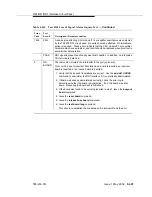
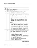
1311
FAIL
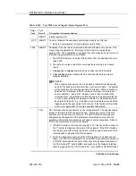
The Integrated CSU (I-CSU) Module Equipment Loopback (ELB) test (#1210)
failed. This test is executedduring ICSU
/T1 sync splitter
power-up/reset (the
TN767E board is physically inserted and the CSU module
/T1 sync splitter
is
already installed) or when the 120A CSU module
/T1 sync splitter
is plugged
on to an already initialized DS1 board. The ELB test is also executed as part of
the command test ds1-loop UUCSS ds1/csu-loopback-tests.
1. Execute test ds1-loop UUCSS ds1/csu-loopback-tests.
2. If the ELB test continues to fail, then either the TN767E board, the CSU
module
/T1 sync splitter
, or the I/O cable between the backplane and the
CSU module
/T1 sync splitter
(or any combination thereof) has failed.
Attempt to isolate the problem to one of these areas. Begin by replacing
the CSU module
/T1 sync splitter
and running the test ds1-loop UUCSS
ds1/csu-loopback-tests command again.
3. If the ELB test continues to fail, then replace the TN767E board and run
test ds1-loop UUCSS ds1/csu-loopback-tests again.
4. If the ELB test continues to fail, the problem could be in the I/O cable
between the backplane and the CSU module
/T1 sync splitter
.
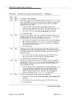
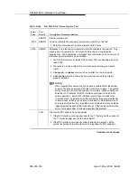
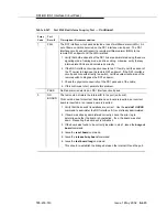
1312
FAIL
The Integrated CSU (I-CSU) Module Repeater Loopback (RLB) test (#1211)
failed. This test is executed during ICSU
/T1 sync splitter
power-up/reset (the
TN767E board is physically inserted and the CSU module
/T1 sync splitter
is
already installed), or when the 120A1 CSU module
/T1 sync splitter
is plugged
on to an already initialized DS1 board. The RLB test is also executed as part of
the command test ds1-loop UUCSS ds1/csu-loopback-tests.
1. Execute test ds1-loop UUCSS ds1/csu-loopback-tests.
2. If the RLB test continues to fail, then replace the CSU module
/T1 sync
splitter
.
3. Run this test again.
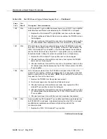
1313
FAIL
The TN767E circuit pack could not deactivate a CPE loop-back jack loop back.
1. Execute test ds1-loop UUCSS end-loopback/span-test.
2. If the attempt to deactivate the CPE loop-back jack is not successful, check
the cabling and investigate the problem at the CPE loop-back jack.
3. Run the test again.
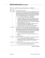
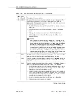
1314
FAIL
The TN767E circuit pack could not deactivate a far-end CSU loop loop-back.
1. Execute test ds1-loop UUCSS end-loopback/span-test.
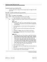
Table 8-245.
Test #138 Loss of Signal Alarm Inquiry Test —
Continued
Error
Code
Test
Result
Description / Recommendation
Continued on next page
Содержание S8700 Series
Страница 50: ...Maintenance Architecture 555 233 143 1 26 Issue 1 May 2002 ...
Страница 74: ...Initialization and Recovery 555 233 143 3 12 Issue 1 May 2002 ...
Страница 186: ...Alarms Errors and Troubleshooting 555 233 143 4 112 Issue 1 May 2002 ...
Страница 232: ...Additional Maintenance Procedures 555 233 143 5 46 Issue 1 May 2002 ...
Страница 635: ...status psa Issue 1 May 2002 7 379 555 233 143 status psa See status tti on page 7 406 ...
Страница 722: ...Maintenance Commands 555 233 143 7 466 Issue 1 May 2002 ...
Страница 1121: ...CARR POW Carrier Power Supply Issue 1 May 2002 8 399 555 233 143 Figure 8 19 Power Distribution Unit J58890CH 1 ...
Страница 1447: ...E DIG RES TN800 reserve slot Issue 1 May 2002 8 725 555 233 143 E DIG RES TN800 reserve slot See ASAI RES ...
Страница 1735: ...LGATE AJ Issue 1 May 2002 8 1013 555 233 143 LGATE AJ See BRI SET LGATE BD See BRI BD LGATE PT See BRI PT ...
Страница 1846: ...Maintenance Object Repair Procedures 555 233 143 8 1124 Issue 1 May 2002 Figure 8 62 TN787 MMI MULTIMEDIA INTERFACE CIRCUIT PACK ...


