


Maintenance-Object Repair Procedures
555-233-143
8-1362
Issue 1 May 2002
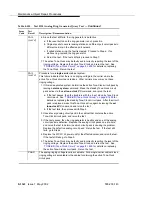
FAIL
(cont’d)
6. Since the test still fails, the ring generator is defective.
a. If the reset button on the ring generator is out, press it in.
b. Originate calls to several analog stations on different port circuit packs in
different carriers in the affected port network.
c. If called stations ring, the fault is cleared. Proceed to Step d. If no
stations ring, replace the ring generator.
d. Rerun the test. If the test still fails, proceed to Step 7.
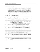
7. The active Tone-Clock may be faulty and incorrectly reporting the level of the
ringing voltage. Replace the active Tone-Clock, and rerun the test. See
‘‘TONE-BD (Tone-Clock Circuit)’’ on page 8-1659
for details on replacing
the Tone-Clock. Rerun the test.
FAIL
(cont’d.)
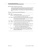
Procedure for a single-carrier cabinet system:
This failure indicates that there is no ringing voltage in the carrier where the
active Tone-Clock circuit pack resides. Other carriers may or may not have
ringing voltage.
1. If this is a duplicated system, determine the active Tone-Clock circuit pack by
issuing a status system command. Make the standby Tone-Clock circuit
pack active via the set tone-clock PC command, and rerun the test.
a. If the test passes, then the trouble is with the “new” stand by Tone-Clock
circuit pack. See
‘‘TONE-BD (Tone-Clock Circuit)’’ on page 8-1659
for
details on replacing the standby Tone-Clock circuit pack. After the circuit
pack is replaced, make this Tone-Clock active again by issuing the set
tone-clock PC command and rerun the test.
b. If the test fails, then proceed with Step 2.
2. Unseat every analog circuit pack in the cabinet that contains the active
Tone-Clock circuit pack, and rerun the test.
3. If the test passes, then the ring generator is healthy and one of the analog
circuit packs is defective. Replace the analog circuit packs one at a time,
and rerun the test to determine which circuit pack is causing the problem.
Replace the defective analog circuit pack. Rerun the test. If the test still
fails, go to Step 4.
4. Replace the WP-91153 power unit for the affected carrier, and rerun the test.
If the test still fails, go to Step 5.
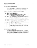
5. The active Tone-Clock may be faulty and incorrectly reporting the level of the
ringing voltage. Replace the active Tone-Clock, and rerun the test. See
‘‘TONE-BD (Tone-Clock Circuit)’’ on page 8-1659
for details on replacing
the active Tone-Clock circuit pack. Rerun the test.
PASS
The analog ringing voltage level is acceptable. For a single-carrier cabinet stack,
ringing voltage is acceptable in the cabinet containing the active Tone-Clock
circuit pack.
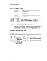
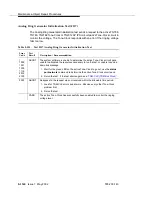
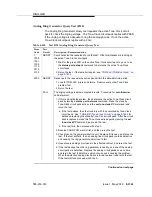
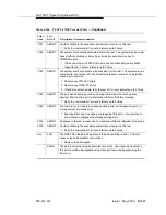
Table 8-554.
Test #118 Analog Ring Generator Query Test —
Continued
Error
Code
Test
Result
Description / Recommendation
Continued on next page
Содержание S8700 Series
Страница 50: ...Maintenance Architecture 555 233 143 1 26 Issue 1 May 2002 ...
Страница 74: ...Initialization and Recovery 555 233 143 3 12 Issue 1 May 2002 ...
Страница 186: ...Alarms Errors and Troubleshooting 555 233 143 4 112 Issue 1 May 2002 ...
Страница 232: ...Additional Maintenance Procedures 555 233 143 5 46 Issue 1 May 2002 ...
Страница 635: ...status psa Issue 1 May 2002 7 379 555 233 143 status psa See status tti on page 7 406 ...
Страница 722: ...Maintenance Commands 555 233 143 7 466 Issue 1 May 2002 ...
Страница 1121: ...CARR POW Carrier Power Supply Issue 1 May 2002 8 399 555 233 143 Figure 8 19 Power Distribution Unit J58890CH 1 ...
Страница 1447: ...E DIG RES TN800 reserve slot Issue 1 May 2002 8 725 555 233 143 E DIG RES TN800 reserve slot See ASAI RES ...
Страница 1735: ...LGATE AJ Issue 1 May 2002 8 1013 555 233 143 LGATE AJ See BRI SET LGATE BD See BRI BD LGATE PT See BRI PT ...
Страница 1846: ...Maintenance Object Repair Procedures 555 233 143 8 1124 Issue 1 May 2002 Figure 8 62 TN787 MMI MULTIMEDIA INTERFACE CIRCUIT PACK ...


