


Maintenance-Object Repair Procedures
555-233-143
8-1724
Issue 1 May 2002
Notes:
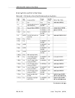
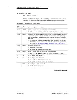
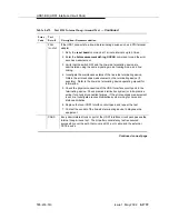
a. Error Type 1 — Indicates that the circuit pack has totally stopped
functioning or is not fully administered. The alarm is logged about
15 minutes after the circuit pack has been removed or 11 minutes after the
SAKI test (#53) fails.
To be fully administered, a UDS1 circuit pack must meet all three of the
following conditions:
1. Have an entry in the circuit plan using the change circuit pack
command
2. Be administered using the add ds1 UUCSS command
3. Be physically inserted into the correct slot
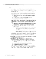
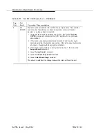
If the circuit pack has an entry in the circuit plan and either of the other two
conditions are not met, a MINOR alarm is logged. To resolve the error
either:
1. Make sure that every condition for administration is met and that a
functioning UDS1 circuit pack is inserted in the correct slot, or
2. Completely remove the UDS1-BD from the system using the
following steps:
a. Remove any administered DS1 trunks, access endpoints or
PRI endpoints associated with the circuit pack from their
trunk groups.
b. Execute the remove ds1 UUCSS and change circuit-pack
UUCSS commands.
If every administration condition is met for this circuit pack and the red LED
is still on, follow the instructions for LED Alarms with Error Type 1 in
Chapter 7.
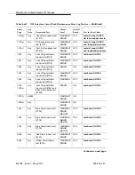
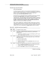
b. Error Type 18 — The UDS1 Interface circuit pack has been busied out by
a busyout board UUCSS command.
c. Error Type 23 — The UDS1-BD circuit pack is not completely
administered. To be fully administered, the UDS1 circuit pack must:
1. Have an entry in the circuit plan using the change circuit-pack
command
2. Be administered using the add ds1 UUCSS command
3. Be physically inserted into the correct slot
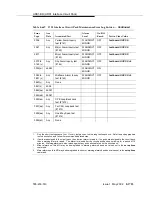
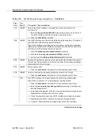
A DS1 (UDS1-BD and DS1-BD) differs from most circuit packs in that
inserting the circuit pack into the switch is not enough to make the board
usable. It must also be administered with the add ds1 command.
Содержание S8700 Series
Страница 50: ...Maintenance Architecture 555 233 143 1 26 Issue 1 May 2002 ...
Страница 74: ...Initialization and Recovery 555 233 143 3 12 Issue 1 May 2002 ...
Страница 186: ...Alarms Errors and Troubleshooting 555 233 143 4 112 Issue 1 May 2002 ...
Страница 232: ...Additional Maintenance Procedures 555 233 143 5 46 Issue 1 May 2002 ...
Страница 635: ...status psa Issue 1 May 2002 7 379 555 233 143 status psa See status tti on page 7 406 ...
Страница 722: ...Maintenance Commands 555 233 143 7 466 Issue 1 May 2002 ...
Страница 1121: ...CARR POW Carrier Power Supply Issue 1 May 2002 8 399 555 233 143 Figure 8 19 Power Distribution Unit J58890CH 1 ...
Страница 1447: ...E DIG RES TN800 reserve slot Issue 1 May 2002 8 725 555 233 143 E DIG RES TN800 reserve slot See ASAI RES ...
Страница 1735: ...LGATE AJ Issue 1 May 2002 8 1013 555 233 143 LGATE AJ See BRI SET LGATE BD See BRI BD LGATE PT See BRI PT ...
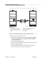
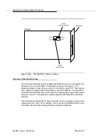
Страница 1846: ...Maintenance Object Repair Procedures 555 233 143 8 1124 Issue 1 May 2002 Figure 8 62 TN787 MMI MULTIMEDIA INTERFACE CIRCUIT PACK ...


