


Maintenance-Object Repair Procedures
555-233-143
8-1796
Issue 1 May 2002
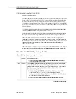
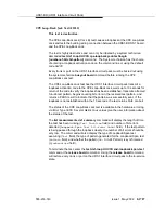
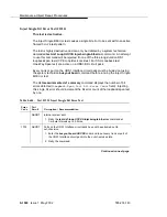
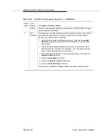
One-Way Span Test (#1214)
This test is destructive.
The One-Way Span test allows 1-way span testing to and from remote test
equipment or another Avaya communications system. This tests all circuitry and
facilities from the local DS1 board to the remote test equipment or other Avaya
communications system.
The test is destructive and can only be initiated by a system technician demanded
test ds1-loop UUCSS one-way-span-test-begin command.
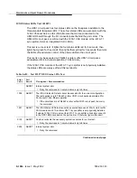
Every trunk or port on the UDS1 Interface circuit pack must be busied out using
the system technician busyout board command before running the One-Way
Span test.
The One-Way Span test has the UDS1 Interface circuit pack transmit a framed
3-in-24 test pattern and attempt to receive and verify the pattern. If the UDS1-BD
board receives a framed 3-in-24 test pattern sent from another Avaya
communications system or test equipment at the far end of the DS1, it begins
counting bit errors within the received pattern.
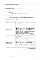
The status of the One-Way Span test is available in the hardware error log via
Error Type 3902. Several distinct Aux values give the user information of the
status of the test.
The list measurements ds1 summary command will display the length of time
the test has been running (
Test Duration
field) and number of bit errors
detected (
Loopback/Span Test Bit-Error Count
field). If the test pattern
is being sent cleanly over the span from the far end, the number of bit errors
should be very low. The
Test Duration
field will show
0
until the test pattern is
received from the far-end. Upon receiving the test pattern, the board will begin
calculating the test duration and number of bit errors. The command will also
display the Loopback/Span test executing (
Test
field), the type of pattern
generated for the Loopback/Span test (
Pattern
field), and whether the pattern
(i.e., 3-in-24 Pattern) is synchronized (
Synchronized
field).
To terminate the test, enter the test ds1-loop UUCSS end-loopback/span-test
command or the release board command. Using the release board command
will restore every trunk or port on the UDS1 Interface circuit pack to the in-service
state.
Содержание S8700 Series
Страница 50: ...Maintenance Architecture 555 233 143 1 26 Issue 1 May 2002 ...
Страница 74: ...Initialization and Recovery 555 233 143 3 12 Issue 1 May 2002 ...
Страница 186: ...Alarms Errors and Troubleshooting 555 233 143 4 112 Issue 1 May 2002 ...
Страница 232: ...Additional Maintenance Procedures 555 233 143 5 46 Issue 1 May 2002 ...
Страница 635: ...status psa Issue 1 May 2002 7 379 555 233 143 status psa See status tti on page 7 406 ...
Страница 722: ...Maintenance Commands 555 233 143 7 466 Issue 1 May 2002 ...
Страница 1121: ...CARR POW Carrier Power Supply Issue 1 May 2002 8 399 555 233 143 Figure 8 19 Power Distribution Unit J58890CH 1 ...
Страница 1447: ...E DIG RES TN800 reserve slot Issue 1 May 2002 8 725 555 233 143 E DIG RES TN800 reserve slot See ASAI RES ...
Страница 1735: ...LGATE AJ Issue 1 May 2002 8 1013 555 233 143 LGATE AJ See BRI SET LGATE BD See BRI BD LGATE PT See BRI PT ...
Страница 1846: ...Maintenance Object Repair Procedures 555 233 143 8 1124 Issue 1 May 2002 Figure 8 62 TN787 MMI MULTIMEDIA INTERFACE CIRCUIT PACK ...


