


Hardware Configurations
555-233-143
2-6
Issue 1 May 2002
The DS1 CONV to EI/SNI cable is a shielded metallic Y-cable held in place at the
EI/SNI port connector by a 4B retainer and at the DS1 CONV port connector by a
4C retainer. The cable end with one 25-pair amphenol connector attaches to the
I/O Plate connector for the EI or SNI. The end with two 25-pair amphenol
connectors attaches to the DS1 CONV I/O plate connector.
The 13-inch cable 846448652 or 847245776 connects the DS1 CONV to a
fiber-optic cable, enabling the DS1 CONV to connect to an EI or SNI at a greater
distance. The cable end with one 25-pair amphenol connector attaches to a
lightwave transceiver using the 846885259 bracket. The end with two 25-pair
amphenol connectors attaches to the DS1 CONV I/O plate connector. The other
end of the fiber-optic cable connects to a lightwave transceiver attached to the I/O
plate connector of the EI or SNI.
An H600-348 cable connects the DS1 CONV cable to a CSU (channel service
unit), which connects to a wall field. (Alternatively, connection is sometimes made
directly from the Y-cable to the wall field. See the pinout for the 50-pin connector
at the end of the Fiber Fault Isolation Procedure in
.) This cable provides from one to four DS1 connections.
One end of the H600-348 cable is plugged into the 50-pin amphenol piggy-back
connector on the 8464486xx cable connected to the DS1CONV port connector.
The other end of the H600-348 cable has four 15-pin sub-miniature D-type
connectors that plug into the CSU. A pinout of this cable appears the end of
‘‘Fault Isolation for Fiber Links’’ on page 4-19
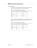
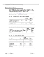
in Chapter 5. H600-348 cables
come in the following lengths:
Group No.
Length
Group No.
Length
G1
25 feet (7.62 m)
G5
125 feet (38.1 m)
G2
50 feet (15.24 m)
G6
200 feet (60.96 m)
G3
75 feet (22.86 m)
G7
400 feet (121.9 m)
G4
100 feet (30.48 m)
G8
650 feet (198 m)
Содержание S8700 Series
Страница 50: ...Maintenance Architecture 555 233 143 1 26 Issue 1 May 2002 ...
Страница 74: ...Initialization and Recovery 555 233 143 3 12 Issue 1 May 2002 ...
Страница 186: ...Alarms Errors and Troubleshooting 555 233 143 4 112 Issue 1 May 2002 ...
Страница 232: ...Additional Maintenance Procedures 555 233 143 5 46 Issue 1 May 2002 ...
Страница 635: ...status psa Issue 1 May 2002 7 379 555 233 143 status psa See status tti on page 7 406 ...
Страница 722: ...Maintenance Commands 555 233 143 7 466 Issue 1 May 2002 ...
Страница 1121: ...CARR POW Carrier Power Supply Issue 1 May 2002 8 399 555 233 143 Figure 8 19 Power Distribution Unit J58890CH 1 ...
Страница 1447: ...E DIG RES TN800 reserve slot Issue 1 May 2002 8 725 555 233 143 E DIG RES TN800 reserve slot See ASAI RES ...
Страница 1735: ...LGATE AJ Issue 1 May 2002 8 1013 555 233 143 LGATE AJ See BRI SET LGATE BD See BRI BD LGATE PT See BRI PT ...
Страница 1846: ...Maintenance Object Repair Procedures 555 233 143 8 1124 Issue 1 May 2002 Figure 8 62 TN787 MMI MULTIMEDIA INTERFACE CIRCUIT PACK ...


