


Maintenance-Object Repair Procedures
555-233-143
8-1592
Issue 1 May 2002
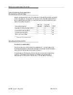
Continue with Procedure 3 if every port circuit pack has been checked, but the
TDM-bus fault is still not resolved.
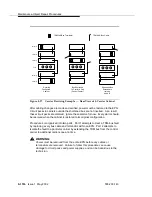
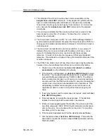
Procedure 3: Removing and Reinserting EPN
Control Circuit Packs
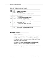
This procedure removes and reinserts an EPN’s control circuit packs, as listed in
the table at the beginning of this section. The following circuit packs should be
tested with this procedure:
■
TN570 Expansion Interface
■
TN768, TN780 Tone-Clock
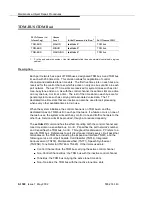
The Tone-Clock circuit pack should be the next-to-last one checked. The
Expansion Interface circuit pack (TN570) should be the last one checked, since
removing this circuit pack disconnects its EPN. In a system with duplicated PNC,
disruption of traffic can be minimized by following the procedure for the standby
TN570 Expansion Interface circuit pack, and then entering reset pnc
interchange. The formerly active Expansion Interface will now be standby and
can be checked without affecting the EPN’s service.
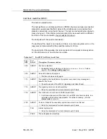
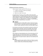
For instructions, at each step in a procedure that requires the removal and/or
replacement of a circuit pack, refer to the documentation for the specific circuit
pack’s MO. Server and/or PNC interchanges may be required to complete these
steps with the least amount of service disruption.
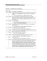
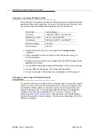
Procedure for EPN with Unduplicated PNC
1. Remove the suspected circuit pack.
2. As in Procedure 2, determine whether the backplane pins behind the
removed circuit pack’s slot are bent.
3. If the backplane pins are bent, do the following:
a. Power down the control carrier as described in the previous warning
statement.
b. Straighten or replace the pins.
c. Insert the same circuit pack.
d. Turn the power back on to reboot the system or to restart the EPN.
e. Run test tdm P to determine whether the TDM-bus fault still exists.
f. If none of the TDM-bus tests fail, the procedure is complete.
g. If some of the TDM-bus tests fail, replace the suspected circuit pack,
and go to step 4.
Содержание S8700 Series
Страница 50: ...Maintenance Architecture 555 233 143 1 26 Issue 1 May 2002 ...
Страница 74: ...Initialization and Recovery 555 233 143 3 12 Issue 1 May 2002 ...
Страница 186: ...Alarms Errors and Troubleshooting 555 233 143 4 112 Issue 1 May 2002 ...
Страница 232: ...Additional Maintenance Procedures 555 233 143 5 46 Issue 1 May 2002 ...
Страница 635: ...status psa Issue 1 May 2002 7 379 555 233 143 status psa See status tti on page 7 406 ...
Страница 722: ...Maintenance Commands 555 233 143 7 466 Issue 1 May 2002 ...
Страница 1121: ...CARR POW Carrier Power Supply Issue 1 May 2002 8 399 555 233 143 Figure 8 19 Power Distribution Unit J58890CH 1 ...
Страница 1447: ...E DIG RES TN800 reserve slot Issue 1 May 2002 8 725 555 233 143 E DIG RES TN800 reserve slot See ASAI RES ...
Страница 1735: ...LGATE AJ Issue 1 May 2002 8 1013 555 233 143 LGATE AJ See BRI SET LGATE BD See BRI BD LGATE PT See BRI PT ...
Страница 1846: ...Maintenance Object Repair Procedures 555 233 143 8 1124 Issue 1 May 2002 Figure 8 62 TN787 MMI MULTIMEDIA INTERFACE CIRCUIT PACK ...


