Maintenance-Object Repair Procedures
555-233-143
8-268
Issue 1 May 2002
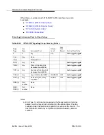
1. Check if the primary DS1 interface circuit pack is inserted in the
carrier with the list configuration board UUCSS command.
2. Verify that the administered primary reference matches the DS1
reference from the network synchronization plan.
3. Test the primary DS1 interface circuit pack with the test board
UUCSS long command. Check the Error Log for DS1-BD or
UDS1-BD errors and see
‘‘DS1-BD (DS1 Interface Circuit Pack)’’
‘‘UDS1-BD (UDS1 Interface Circuit Pack)’’ on page 8-1707
resolve any errors associated with the primary DS1 (DS1 or UDS1)
interface circuit pack. If the only errors against DS1-BD or
UDS1-BD are slip errors, then follow the procedures described in
the troubleshooting section above. If no errors are listed in the Error
Log for the primary DS1 interface circuit pack, continue with the
following steps.
4. Test the active Tone-Clock circuit in the master port network with the
test Tone-Clock UUC long command. Check the Error Log for
TDM-CLK errors and verify that TDM Bus Clock Test #148 (TDM
Bus Clock Circuit Status Inquiry test) passes successfully. If Test
#148 fails with an Error Code 2 through 32, see
to resolve the problem.
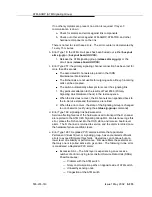
b. Error Type 257: problem with the secondary DS1 reference. It is cleared
when the secondary reference is restored. Refer to note (a) to resolve this
error substituting secondary for primary in the preceding resolution steps.
c. Error Type 513: the ATM switch clock is inferred to be providing the timing
source for the system. The primary and secondary (if administered) are
not providing a valid timing signal. Investigate errors 1 and 257 to resolve
this error.
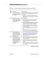
d. Error Type 1537: over half of the DS1s that are administered with slip
detection enabled through the
Slip Detection?
field set to y are
experiencing slips.
e. Error Type 1793: inferred excessive switching of system synchronization
references has occurred. When this error occurs, it is inferred that the ATM
switch clock has become the synchronization reference for the system.
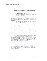
1. Check for timing loops and resolve any loops that exist.
2. Test the active Tone-Clock circuit in the master port network with the
test Tone-Clock UUC long command.
Check the Error Log for TDM-CLK errors, and verify that TDM Bus
Clock Circuit Status Inquiry test (#148) passes successfully.
If Test #148 fails with an Error Code 2–32, see
to resolve the problem. If not, continue
with the following steps.
3. For Duplicated Tone-Clock circuit packs in the master port network:
Switch Tone-Clock circuit packs on the master port network with the
set Tone-Clock UUC command.
Содержание S8700 Series
Страница 50: ...Maintenance Architecture 555 233 143 1 26 Issue 1 May 2002 ...
Страница 74: ...Initialization and Recovery 555 233 143 3 12 Issue 1 May 2002 ...
Страница 186: ...Alarms Errors and Troubleshooting 555 233 143 4 112 Issue 1 May 2002 ...
Страница 232: ...Additional Maintenance Procedures 555 233 143 5 46 Issue 1 May 2002 ...
Страница 635: ...status psa Issue 1 May 2002 7 379 555 233 143 status psa See status tti on page 7 406 ...
Страница 722: ...Maintenance Commands 555 233 143 7 466 Issue 1 May 2002 ...
Страница 1121: ...CARR POW Carrier Power Supply Issue 1 May 2002 8 399 555 233 143 Figure 8 19 Power Distribution Unit J58890CH 1 ...
Страница 1447: ...E DIG RES TN800 reserve slot Issue 1 May 2002 8 725 555 233 143 E DIG RES TN800 reserve slot See ASAI RES ...
Страница 1735: ...LGATE AJ Issue 1 May 2002 8 1013 555 233 143 LGATE AJ See BRI SET LGATE BD See BRI BD LGATE PT See BRI PT ...
Страница 1846: ...Maintenance Object Repair Procedures 555 233 143 8 1124 Issue 1 May 2002 Figure 8 62 TN787 MMI MULTIMEDIA INTERFACE CIRCUIT PACK ...


