


Maintenance-Object Repair Procedures
555-233-143
8-1728
Issue 1 May 2002
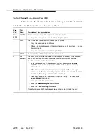
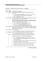
p. Error Type 1312 — RLB failure. This error occurs when the Repeater
Loopback (RLB) test fails for the Integrated CSU (I-CSU) module/T1 sync
splitter or for the 402A or 403A E1 synchronization splitter. This test is
executed by the I-CSU/E1SS during I-CSU/E1SS power-up/reset (i.e., DS1
board physically inserted and 120A1 CSU module or the 401A T1 sync
splitter, or the 402A or 403A E1SS is already installed) or when the 120A1
CSU module or the 401A T1 sync splitter, or the 402A or 403A E1SS is
plugged on to an already initialized DS1 board.
NOTE:
For the I-CSU/T1 sync splitter only, the RLB test is also executed
as part of the command test ds1-loop UUCSS
ds1/csu-loopback-tests. Attempt to clear the alarm using the
commands busyout board UUCSS, test ds1-loop UUCSS
ds1/csu-loopback-tests, release board UUCSS. If the RLB test
continues to fail, then the CSU module needs to be replaced.
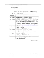
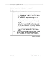
q. Error Type 1313 — CPE Loop-Back Jack deactivation error. This error
occurs when the UDS1 circuit pack could not deactivate a CPE Loop-Back
Jack on power-up/reset or upon software request.
Attempt to clear the alarm using the commands busyout board UUCSS,
test ds1-loopback UUCSS end-loopback/span-test, release board
UUCSS. If the attempt to deactivate the CPE Loop-Back Jack continues to
fail, other steps must be taken to deactivate the loopback.
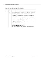
r. Error Type 1314 — Far CSU Loopback deactivation error. This error
occurs when the UDS1 circuit pack could not deactivate a far-end CSU
loop back on power-up/reset or upon software request.
Attempt to clear the alarm using the commands busyout board UUCSS,
test ds1-loop UUCSS end-loopback/span-test, release board UUCSS.
If the attempt to deactivate the Far CSU loop back continues to fail, then
escalate the problem.
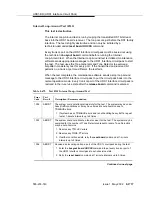
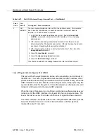
s. Error Types 1400, 1401 — Echo Cancellation errors are logged when:
■
Error 1400 - Echo canceller function failed. The Echo Canceller
Function test, which is executed by firmware, failed.
■
Error 1401 - Echo canceller memory failed. The Echo Canceller
Memory test, which is executed by firmware, failed.
Echo Cancellation is no longer being supplied by the board. Clear the
alarm using the following commands: busyout board UUCSS, test board
UUCSS long, release board UUCSS. If Test #1420 (Echo Canceler test)
fails, replace the circuit pack.
t. Error type 1537 — LAN Bus Timeout Error. This error occurs when the
circuit pack transmits too many bytes on the LAN bus for a single frame.
This condition may be caused by an on-board fault or by faulty data
received on one of the circuit pack’s external ports. If any of the ports on
this circuit pack are alarmed, refer to the repair procedures for those MOs.
Содержание S8700 Series
Страница 50: ...Maintenance Architecture 555 233 143 1 26 Issue 1 May 2002 ...
Страница 74: ...Initialization and Recovery 555 233 143 3 12 Issue 1 May 2002 ...
Страница 186: ...Alarms Errors and Troubleshooting 555 233 143 4 112 Issue 1 May 2002 ...
Страница 232: ...Additional Maintenance Procedures 555 233 143 5 46 Issue 1 May 2002 ...
Страница 635: ...status psa Issue 1 May 2002 7 379 555 233 143 status psa See status tti on page 7 406 ...
Страница 722: ...Maintenance Commands 555 233 143 7 466 Issue 1 May 2002 ...
Страница 1121: ...CARR POW Carrier Power Supply Issue 1 May 2002 8 399 555 233 143 Figure 8 19 Power Distribution Unit J58890CH 1 ...
Страница 1447: ...E DIG RES TN800 reserve slot Issue 1 May 2002 8 725 555 233 143 E DIG RES TN800 reserve slot See ASAI RES ...
Страница 1735: ...LGATE AJ Issue 1 May 2002 8 1013 555 233 143 LGATE AJ See BRI SET LGATE BD See BRI BD LGATE PT See BRI PT ...
Страница 1846: ...Maintenance Object Repair Procedures 555 233 143 8 1124 Issue 1 May 2002 Figure 8 62 TN787 MMI MULTIMEDIA INTERFACE CIRCUIT PACK ...


