


DS1-FAC (DS1 Facility)
Issue 1 May 2002
8-661
555-233-143
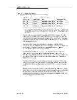
The primary facility on the TN1654 DS1 CONV circuit pack is restricted to facility
A or facility B. The TN1654 provides fixed packet bandwidth of 192 Kbps while
the TN574 provides packet bandwidth of up to 1408 Kbps with a dynamic
allocation mechanism that could change packet/circuit use of individual channels.
The first three 64 Kbps channels on the primary facility of the TN1654 are
reserved as the packet channels. The DS1 control channel will be Channel 24 in
T1 mode and Channel 31 in E1 mode. In T1 format the TN1654 provides 24
circuit channels for use on non-primary facilities and 20 circuit channels on the
primary facility. E1 format provides 31 circuit channels for use on non-primary
facilities and 27 circuit channels on the primary facility.
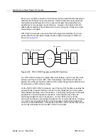
When there are alarms on the packet facility, DS1 CONV circuit pack firmware
changes the mapping of the DS1 channels to move the packet traffic to another
facility. On TN574 DS1 CONV boards, the packet traffic will be moved to another
“Digital Data Compatible” facility (as indicated on the fiber link administration
screen). On TN1654 DS1 CONV boards, the packet traffic will be moved to either
facility A or B if available. This mapping is done to keep the packet service
operational at all times as the system control links are carried on these packet
connections. When packet traffic is moved to another facility, circuit connections
on the new facility are torn down and circuit connections on the old (faulty) facility
are re-mapped to the new packet facility.
After firmware initialization, facility A, the first facility, is chosen as the default
primary facility for both DS1 CONV boards.
The TN574 DS1 CONV has seven LEDs that provide an indication of the state of
the DS1 CONV circuit pack and the DS1 facilities. There is a yellow, a green, and
a red LED under software and/or firmware control. There are four Green LEDs
under hardware control that indicate, for each DS1 facility, whether a receive
signal is present for the DS1 facility. From top to bottom these green LEDs
correspond to DS1 facilities A, B, C, and D respectively. If one of the four green
LED is on, it indicates a signal is present, but it does not imply that the signal is
using the correct framing format (ESF or D4) or line coding (ZCS or B8ZS). See
section DS1C-BD for the description of the red, the green, and the amber LEDs
on the DS1 CONV circuit pack.
The TN1654 DS1 CONV board has eleven LEDs on its faceplate. The top three
system standard LEDs (yellow, green and red) are used to provide an indication of
the state of the DS1 CONV board. The bottom four LEDs on the TN1654 board
are labeled SPAN LEDs. These LEDs are under firmware control. If the facility is
not administered, then the LED is not lit. The LED is lit amber if the facility is
running alarm free. If the facility is detecting either a red alarm (loss-of-signal or
loss-of-frame), a yellow alarm (remote frame alarm) or a blue alarm (AIS signal)
then the LED is lit red. See section DS1C-BD for a complete description off all the
LEDs.
The TN1654 DS1 CONV circuit pack supports the Wideband Switching feature.
The TN574 DS1 CONV does not.
Содержание S8700 Series
Страница 50: ...Maintenance Architecture 555 233 143 1 26 Issue 1 May 2002 ...
Страница 74: ...Initialization and Recovery 555 233 143 3 12 Issue 1 May 2002 ...
Страница 186: ...Alarms Errors and Troubleshooting 555 233 143 4 112 Issue 1 May 2002 ...
Страница 232: ...Additional Maintenance Procedures 555 233 143 5 46 Issue 1 May 2002 ...
Страница 635: ...status psa Issue 1 May 2002 7 379 555 233 143 status psa See status tti on page 7 406 ...
Страница 722: ...Maintenance Commands 555 233 143 7 466 Issue 1 May 2002 ...
Страница 1121: ...CARR POW Carrier Power Supply Issue 1 May 2002 8 399 555 233 143 Figure 8 19 Power Distribution Unit J58890CH 1 ...
Страница 1447: ...E DIG RES TN800 reserve slot Issue 1 May 2002 8 725 555 233 143 E DIG RES TN800 reserve slot See ASAI RES ...
Страница 1735: ...LGATE AJ Issue 1 May 2002 8 1013 555 233 143 LGATE AJ See BRI SET LGATE BD See BRI BD LGATE PT See BRI PT ...
Страница 1846: ...Maintenance Object Repair Procedures 555 233 143 8 1124 Issue 1 May 2002 Figure 8 62 TN787 MMI MULTIMEDIA INTERFACE CIRCUIT PACK ...


