


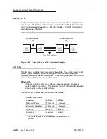


SNC-LINK (Switch Node Clock Link)
Issue 1 May 2002
8-1425
555-233-143
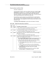
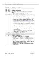
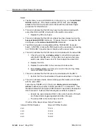
3. Verify that the SNI the SNC is complaining about exists in the slot
indicated by the error code. If the SNI does not exist:
If you do not intend to replace the SNI:
a. Remove the SNI from circuit pack administration via change
circuit-pack.
b. If the error remains, readminister the SNI circuit pack and
then remove it from administration again.
c. If the problem persists, replace the active SNC circuit pack.
Otherwise:
a. Insert an SNI circuit pack.
If this step does not apply, continue with the following steps.
4. Replace the SNI circuit pack that the SNC is complaining about.
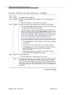
5. Retry the command. If this error is still in the error log, continue with
the following steps.
6. Replace the SNC circuit pack.
7. If a standby SNC (the one with its yellow LED off) has this error,
escalate the problem. (Status switch-node will also display the
active and standby SNCs.)
8. Retry the command. If this error is still in the error log, escalate the
problem.
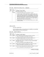
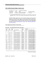
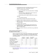
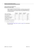
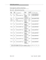
System Technician-Demanded Tests:
Descriptions and Error Codes
Always investigate tests in the order presented in the table below when inspecting
errors in the system. For example, by clearing error codes associated with the
Configuration audit (#759), you may also clear errors generated from other tests
in the testing sequence.
See
‘‘SNC-BD (Switch Node Clock Circuit Pack)’’ on page 8-1384
for descriptions
of tests and results.
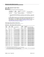
Order of Investigation
Short Test
Sequence
Long Test
Sequence
Reset Board
Sequence
D/ND
1
1.
D = Destructive, ND = Nondestructive
Configuration audit (#759)
X
X
ND
Failure audit (#777)
X
X
ND
Processor Route audit (#760)
X
ND
SNC On-Board test (#778)
X
X
ND
TPN test (#779)
X
X
ND
Switch Node Clock Reset test (#780)
X
D
Содержание S8700 Series
Страница 50: ...Maintenance Architecture 555 233 143 1 26 Issue 1 May 2002 ...
Страница 74: ...Initialization and Recovery 555 233 143 3 12 Issue 1 May 2002 ...
Страница 186: ...Alarms Errors and Troubleshooting 555 233 143 4 112 Issue 1 May 2002 ...
Страница 232: ...Additional Maintenance Procedures 555 233 143 5 46 Issue 1 May 2002 ...
Страница 635: ...status psa Issue 1 May 2002 7 379 555 233 143 status psa See status tti on page 7 406 ...
Страница 722: ...Maintenance Commands 555 233 143 7 466 Issue 1 May 2002 ...
Страница 1121: ...CARR POW Carrier Power Supply Issue 1 May 2002 8 399 555 233 143 Figure 8 19 Power Distribution Unit J58890CH 1 ...
Страница 1447: ...E DIG RES TN800 reserve slot Issue 1 May 2002 8 725 555 233 143 E DIG RES TN800 reserve slot See ASAI RES ...
Страница 1735: ...LGATE AJ Issue 1 May 2002 8 1013 555 233 143 LGATE AJ See BRI SET LGATE BD See BRI BD LGATE PT See BRI PT ...
Страница 1846: ...Maintenance Object Repair Procedures 555 233 143 8 1124 Issue 1 May 2002 Figure 8 62 TN787 MMI MULTIMEDIA INTERFACE CIRCUIT PACK ...


