6
6.15 Spindle positioning (from SW 5.1)
6-606
Siemens AG 2005 All Rights Reserved
SIMODRIVE 611 universal Description of Functions (FBU) – 04.05 Edition
If the drive has still not been referenced, it is automatically referenced
after activating the ”spindle positioning on” function.
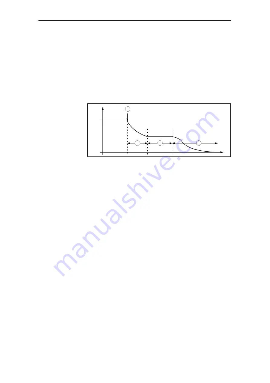
The positioning operation is executed via the position controller and is
carried–out in several phases:
1. Selecting the ”spindle positioning on” function via terminal or PRO-
FIBUS–DP in the ”n–set” mode
2. Traversing to the search velocity
3. Traversing with search velocity and searching for the zero mark
(BERO)
4. Braking to the 1st target position (angle)
n
act
t
Command, spindle positioning on
1
2
3
4
Fig. 6-84 Example, spindle positioning
If the drive is at the 1st target position, then the additional target posi-
tions can be approached immediately by selecting another traversing
block.
In order to guarantee a defined changeover to the next position (via
terminals), only one bit should be changed when selecting the travers-
ing block.
If, when the controller is inhibited, the spindle is pushed (pressed) out
of a parameterized tolerance window, then the position actual value is
corrected (tracked). If the controller is then re–enabled, the spindle re-
mains at that particular position. It is only re–positioned again if ”spindle
positioning” is activated.
The following parameters are available for the ”spindle positioning”
function:
P0080
Block number (traversing blocks)
P0081
Position reference value (traversing blocks)
P0082
(Search) velocity (traversing blocks)
P0083
Acceleration override
P0084
Deceleration override
P0087
(Spindle) positioning mode
P0102
Maximum velocity
P0103
Maximum acceleration
P0104
Maximum deceleration
P0125
Spindle positioning active
P0126
Spindle positioning, zero mark tolerance window
P0127
Spindle positioning, setting the internal zero mark
P0128
Spindle positioning, offset, zero mark
Positioning
Parameter
overview
(refer to Chapter
A.1)
6 Description of the Functions
01.99
02.02
! not 611ue !
10.04


