■
If specified, Revit Architecture does not retain the end point value during creation of the blend. If you
need to make multiple blends with the same end point, first sketch the blends, then select them, and
then apply the end point.
Creating Solid Extrusions
Revit Architecture uses extrusions to define 3D geometry for families. You create an extrusion by defining
a 2D sketch on a plane; Revit Architecture then extrudes that sketch between a start and an end point.
The following procedure is a general method for creating an extrusion. Steps may vary depending on your
design intent. You can also create massing shapes using the Extrude command. Access massing commands
through the Massing tab of the Design Bar. For more information on massing, see
Conceptual Design with
Massing Studies
on page 517.
1
In the Family Editor, click Solid Form
➤
Solid Extrusion on either the Modelling menu or the
Family tab of the Design Bar.
2
If the Select a Work Plane dialog opens, choose a work plane to draw the extrusion. See
Sketching
and Work Planes
on page 265.
3
Sketch a shape. The profile sketch can be a single-closed loop or multiple closed loops that do
not intersect. For more information about the sketching tools, see
Sketching
on page 251.
TIP
By default, Revit Architecture uses a start point of 0. You can change this value and the end point
value prior to sketching the shape. While in sketch mode, click
. In the Element Properties
dialog, specify values for the extrusion end and start. See
Element Properties Dialog
on page 75.
4
After creating a sketch shape, click Finish Sketch.
Revit Architecture completes the extrusion and returns you to the view in which you started
the extrusion. If you did not specify a start and end point, Revit Architecture calculates a depth
for you, based on the size of the shape you sketched.
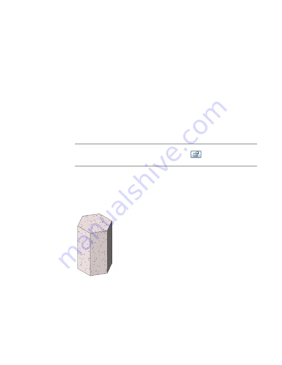
To see the new extrusion, switch to a 3D view.
Sample polygonal concrete isolated foundation extrusion
5
Select the view visibility of the extrusion. See
Setting Family Geometry Visibility
on page 360.
6
When you have created the extrusion you like, save it or click Finish Family if you are creating
an in-place family.
386 | Chapter 8 Creating Your Own Components (Families)
Содержание 24000-000000-9860 - Revit Architecture - PC
Страница 1: ...Revit Architecture 2009 User s Guide April 2008 240A1 050000 PM02A ...
Страница 4: ......
Страница 56: ...18 ...
Страница 116: ...78 Chapter 3 Revit Essentials ...
Страница 172: ...134 Chapter 4 ProjectViews ...
Страница 178: ...Schedule with Grid Lines Schedule with Grid Lines and an Outline 140 Chapter 4 ProjectViews ...
Страница 352: ...Defining the first scale vector Defining the second scale vector 314 Chapter 7 Editing Elements ...
Страница 554: ...516 ...
Страница 739: ...Curtain wall Curtain Grid Curtain Walls Curtain Grids and Mullions 701 ...
Страница 898: ...Pile caps with multiple piles Rectangular and triangular pile caps 860 Chapter 12 Working with Structural Components ...
Страница 1004: ...966 ...
Страница 1136: ...1098 ...
Страница 1226: ...1188 ...
Страница 1250: ...1212 ...
Страница 1276: ...1238 Chapter 20 Design Options ...
Страница 1310: ...1272 ...
Страница 1366: ...1328 ...
Страница 1406: ...1368 ...


