Reference Lines
You can use reference lines to create a parametric family skeleton that elements of the family can attach to.
For example, you would use reference lines to parametrically maintain the angular relationships within a
web, or use it to precisely control the angle of a door swing. Angular parameters applied to a reference line
also control the elements attached to its face.
In both look and behavior, reference lines are very similar to model lines. However, there are significant
differences between model lines and reference lines. For example, reference lines are annotation objects
with their own category. When selected, they display dual faces. When printing, their visibility is affected
by the Hide ref/work planes option.
Straight reference lines provide 2 planes for you to sketch on. One plane is parallel to the work plane of the
line itself; the second plane is perpendicular to that plane. Both planes go through the reference line. The
planes display when the reference line is selected, when the reference line is highlighted, or when using the
Work Plane tool. When selecting a work plane, you can place the cursor over a reference line and use the
Tab key to switch between the 2 faces. The plane in which the line was sketched always displays first. You
can also create arc reference lines, however, they do not define any planes.
Reference Line Behavior in the Project
Once a family is loaded into a project, the behavior of Reference Lines is identical to that of Reference Planes.
Reference Lines have no visibility property, they are generally invisible in a project and do not highlight
when the instance is selected. They will highlight and generate shape handles in the same contexts as
Reference Planes currently do, depending on their Reference property.
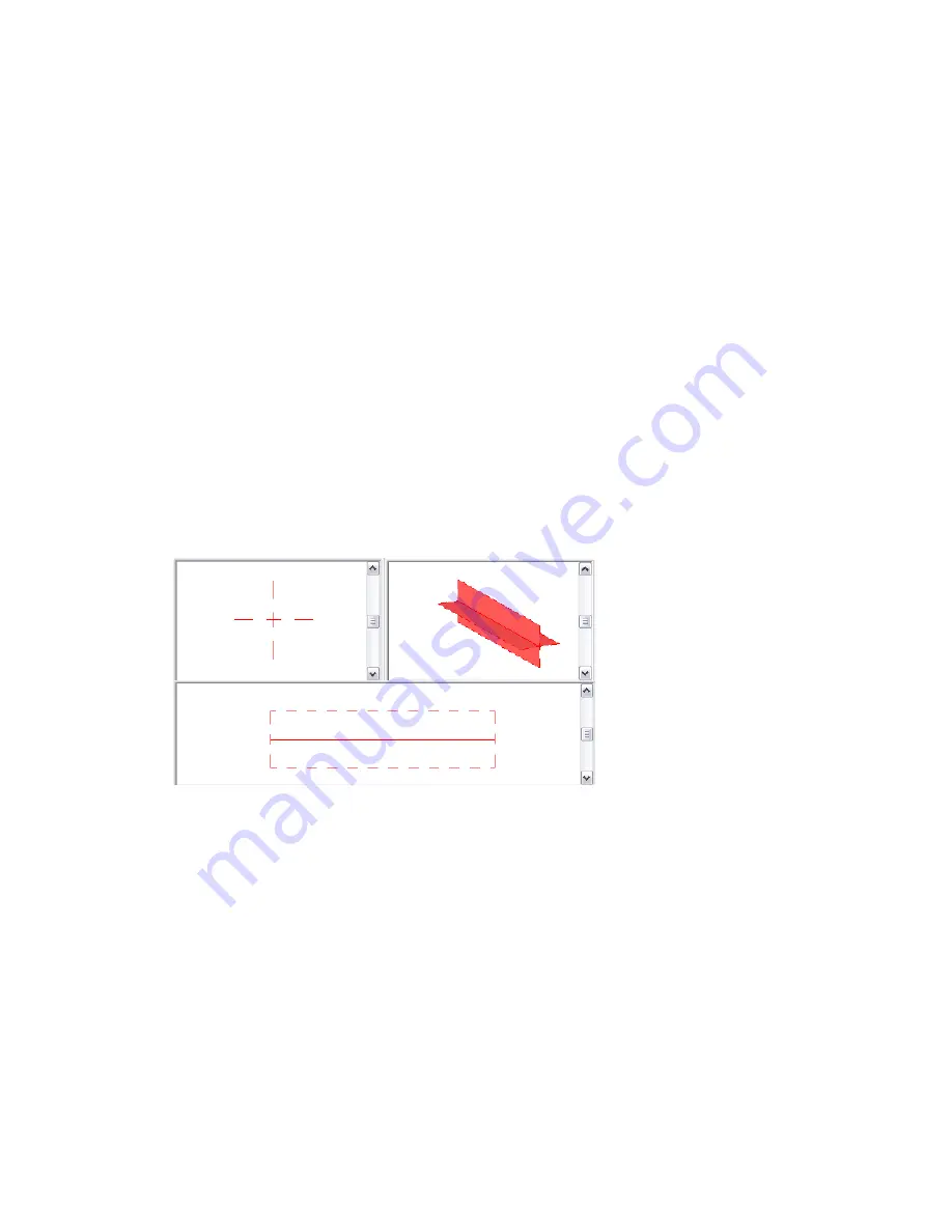
Selected reference line in multiple views
Adding a Reference Line
While in the Family Editor, you can add a reference line in any view and use the same drawing tools and
techniques used when adding model lines. When you sketch a reference line, it displays as a single line.
In a view where the model graphics are set to hidden line or wireframe, the sketched line displays as a solid
line and the plane extents display with dashed lines.
To add a reference line:
1
On the Design Bar, click Reference Lines.
2
Using the drawing tools on the Options Bar, sketch the line.
The line displays as a solitary solid line until selected or when highlighted during preselection.
346 | Chapter 8 Creating Your Own Components (Families)
Содержание 24000-000000-9860 - Revit Architecture - PC
Страница 1: ...Revit Architecture 2009 User s Guide April 2008 240A1 050000 PM02A ...
Страница 4: ......
Страница 56: ...18 ...
Страница 116: ...78 Chapter 3 Revit Essentials ...
Страница 172: ...134 Chapter 4 ProjectViews ...
Страница 178: ...Schedule with Grid Lines Schedule with Grid Lines and an Outline 140 Chapter 4 ProjectViews ...
Страница 352: ...Defining the first scale vector Defining the second scale vector 314 Chapter 7 Editing Elements ...
Страница 554: ...516 ...
Страница 739: ...Curtain wall Curtain Grid Curtain Walls Curtain Grids and Mullions 701 ...
Страница 898: ...Pile caps with multiple piles Rectangular and triangular pile caps 860 Chapter 12 Working with Structural Components ...
Страница 1004: ...966 ...
Страница 1136: ...1098 ...
Страница 1226: ...1188 ...
Страница 1250: ...1212 ...
Страница 1276: ...1238 Chapter 20 Design Options ...
Страница 1310: ...1272 ...
Страница 1366: ...1328 ...
Страница 1406: ...1368 ...


