


CAN Control
CAN Core
CANIF2CRQ
CANIF2CMSK
CANIF2MSK1
CANIF2MSK2
CANIF2ARB1
CANIF2ARB2
CANIF2MCTL
CANIF2DA1
Message Object
Registers
CANNWDA1
CANTXRQ1
CANTXRQ2
CANNWDA2
CANMSG1INT
CANMSG2INT
CANMSG1VAL
CANMSG2VAL
CAN Tx
CANINT
CANTST
CANBRPE
CANERR
CANCTL
CANSTS
CANBIT
CAN Interface 1
CANIF1CRQ
CANIF1CMSK
CANIF1MSK1
CANIF1MSK2
CANIF1ARB1
CANIF1ARB2
CANIF1MCTL
CANIF1DA1
CANIF1DA2
CANIF1DB1
CANIF1DB2
CAN Interface 2
APB
Interface
APB Pins
Message RAM
32 Message Objects
CAN Rx
CANIF2DA2
CANIF2DB1
CANIF2DB2
Introduction
787
SLAU723A – October 2017 – Revised October 2018
Copyright © 2017–2018, Texas Instruments Incorporated
Controller Area Network (CAN) Module
11.1 Introduction
Controller Area Network (CAN) is a multicast, shared serial bus standard for connecting electronic control
units (ECUs). CAN was specifically designed to be robust in electromagnetically-noisy environments and
can use a differential balanced line like RS-485 or a more robust twisted-pair wire. Originally created for
automotive purposes, CAN is also used in many embedded control applications (such as industrial and
medical). Bit rates up to 1 Mbps are possible at network lengths less than 40 meters. Decreased bit rates
allow longer network distances (for example, 125 kbps at 500 meters).
Two CAN units support the following features:
•
CAN protocol version 2.0 part A/B
•
Bit rates up to 1 Mbps
•
32 message objects with individual identifier masks
•
Maskable interrupt
•
Disable Automatic Retransmission mode for Time-Triggered CAN (TTCAN) applications
•
Programmable loopback mode for self-test operation
•
Programmable FIFO mode enables storage of multiple message objects
•
Gluelessly attaches to an external CAN transceiver through the CANnTX and CANnRX signals
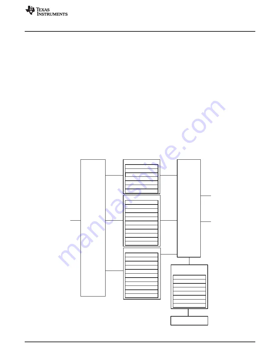
11.2 Block Diagram
shows the CAN Controller block diagram.
Figure 11-1. CAN Controller Block Diagram


