


Initialization and Configuration
1092
SLAU723A – October 2017 – Revised October 2018
Copyright © 2017–2018, Texas Instruments Incorporated
External Peripheral Interface (EPI)
completed. If the system is running at 30 to 50 MHz, wait 2 EPI clock cycles after clearing the SLEEP
bit before executing nonblocking reads, or normal reads and writes. If the system is configured to
greater than 50 MHz, wait 5 EPI clock cycles before read and write transactions. For all other
configurations, wait 1 EPI clock.
The SIZE field of the EPISDRAMCFG register must be configured correctly based on the amount of
SDRAM in the system.
The FREQ field must be configured according to the value that represents the range being used. Based
on the range selected, the number of external clocks used between certain operations (for example,
PRECHARGE or ACTIVATE) is determined. If a higher frequency is given than is used, then the only
downside is that the peripheral is slower (uses more cycles for these delays). If a lower frequency is given,
incorrect operation occurs.
For timing details for the SDRAM mode, see the device-specific data sheet.
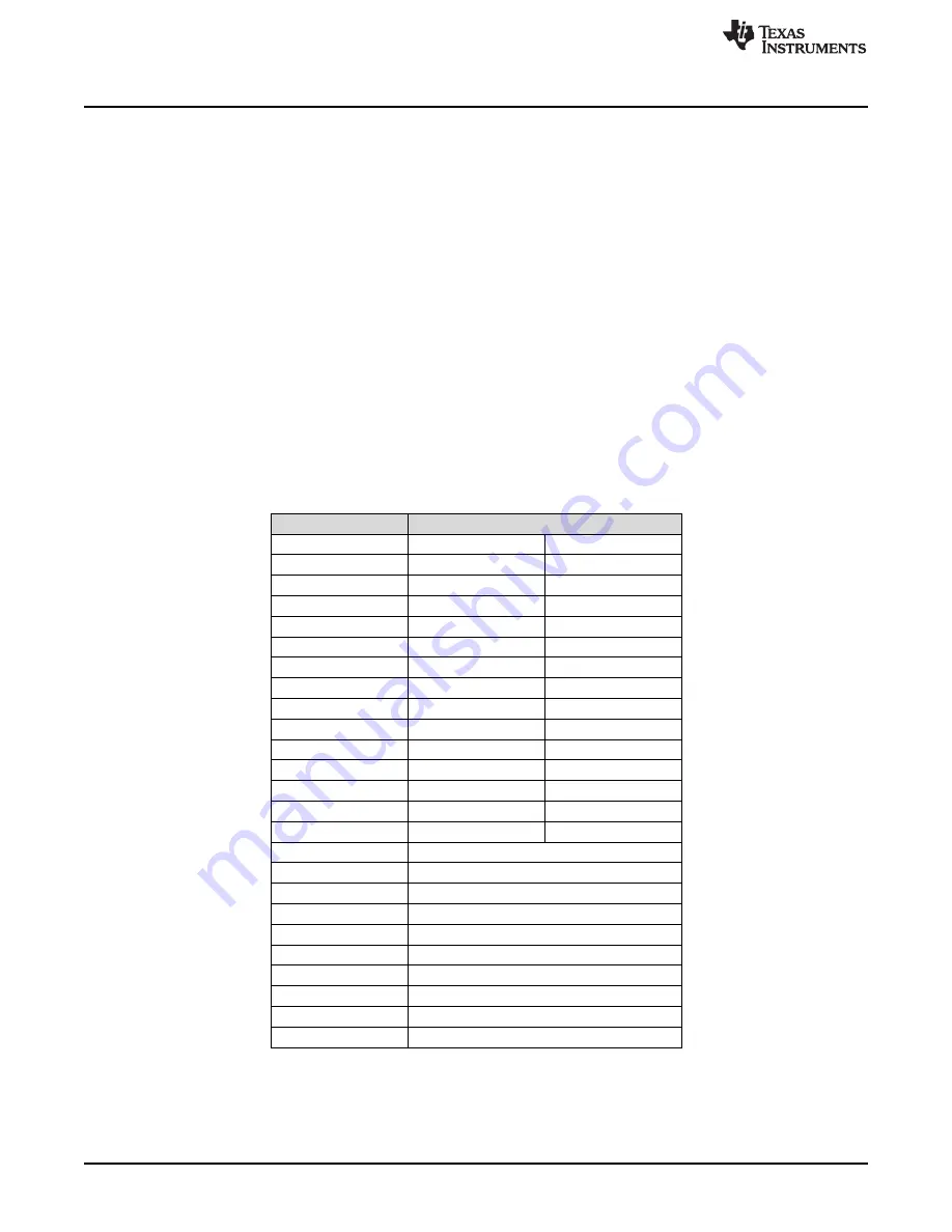
16.4.2.1 External Signal Connections
defines how EPI module signals should be connected to SDRAMs. The table applies when
using a x16 SDRAM up to 512 megabits. The EPI signals must use 8-mA drive when interfacing to
SDRAM, see
. Any unused EPI controller signals can be used as GPIOs or another
alternate function.
(1)
If two signals are listed, connect the EPI signal to both pins.
(2)
Only for 256- or 512-megabit SDRAMs
Table 16-2. EPI SDRAM x16 Signal Connections
EPI Signal
SDRAM Signal
(1)
EPI0S0
A0
D0
EPI0S1
A1
D1
EPI0S2
A2
D2
EPI0S3
A3
D3
EPI0S4
A4
D4
EPI0S5
A5
D5
EPI0S6
A6
D6
EPI0S7
A7
D7
EPI0S8
A8
D8
EPI0S9
A9
D9
EPI0S10
A10
D10
EPI0S11
A11
D11
EPI0S12
A12
(2)
D12
EPI0S13
BA0
D13
EPI0S14
BA1
D14
EPI0S15
D15
EPI0S16
DQML
EPI0S17
DQMH
EPI0S18
CASn
EPI0S19
RASn
EPI0S20-EPI0S27
Not used
EPI0S28
WEn
EPI0S29
CSn
EPI0S30
CKE
EPI0S31
CLK


