2-28-(5)
Density Data
Section 2-28
6.
If additional figures are to be drawn, select Add.
7.
Repeat steps 4 to 6 as necessary to create the desired shape.
8.
After drawing is completed, select End.
The measurement region will be registered and the screen in (1.) will re-
turn. The measurement region will be displayed with a + cursor at the cen-
ter of gravity.
CHECK
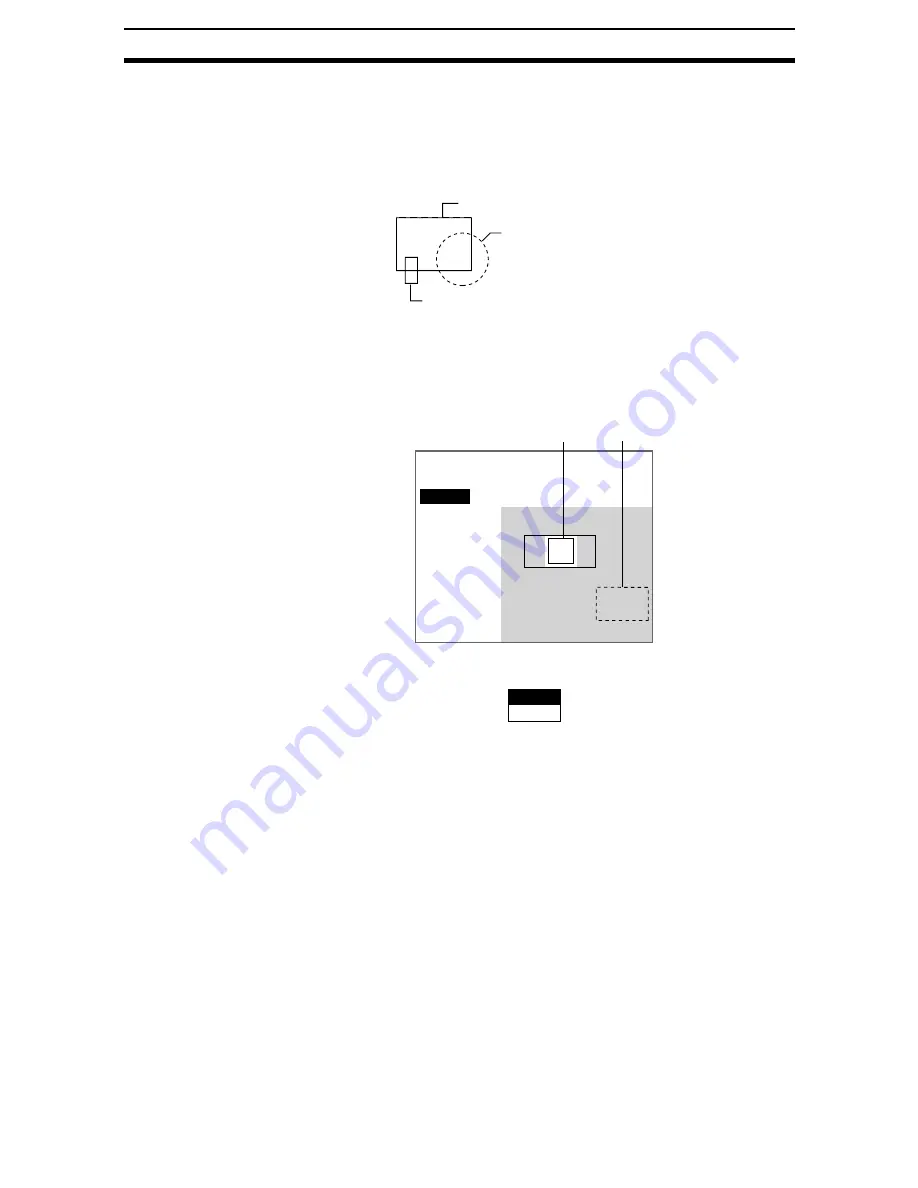
Figures drawn using OR mode are displayed with solid lines and figures
drawn using NOT mode are displayed with dotted lines.
Correcting or Clearing Figures
1.
In the screen for step 5 above, select the figure to be changed or cleared
using the Up and Down Keys and press the ENT Key.
The figure for the figure number selected using the cursor will be displayed
with solid lines. The selections Correct and Clear will be displayed.
2.
Select either Correct or Clear and press the ENT Key.
If Correct is selected, the cursor will be displayed. Correct the size and po-
sition of the figure as desired.
If Clear is selected, the selected figure will be cleared.
Figure 1 (drawn using OR)
Figure 2 (drawn using NOT)
Figure 3 (drawn using OR)
Region
Figure 0
Add
Figure0
Figure1
End
Figure 1
Correct
Clear


