2-12-(18)
Detecting Binary Defects
Section 2-12
5.
Select Binary.
The Binary Levels Settings Screen will be displayed.
The rest of the procedure is the same as outlined under
6HWWLQJWKH
%LQDU\/HYHO
.
SeeAlso
Refer to page 2-12-(4).
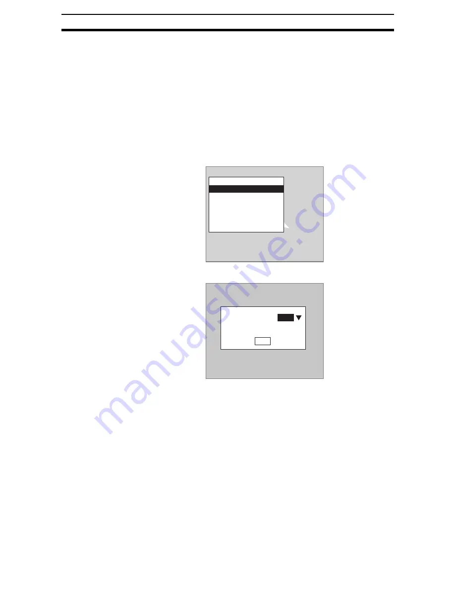
STEP 2: Setting Measurement Conditions
Set the binary tracking function when the variations in measurement object
color or other factors prevent correct measurement with stable binary levels. If
the binary tracking function is set to ON, the Controller will automatically adjust
the binary levels in line with the brightness of the input image. The default set-
ting is OFF.
1.
Select Measurement conditions.
The Measurement Conditions Settings Screen will be displayed.
2.
Select either ON or OFF.
3.
Select End.
The settings will be registered and the screen in (1.) will return.
STEP 3: Drawing Measurement Regions
When a measurement region is drawn, measurement is performed for the dis-
played image and the results are registered as the reference values (area,
center of gravity, and axis).
CHECK
Regions can be created by combining up to 3 different figures. Regions with
difficult shapes can be drawn and sections not to be measured can be left out
of the region by combining different figures.
Region0(Gravity and axis)
Binary
Measurement conditions
Region
Reference registration
Judgement conditions
Detailed conditions
Clear
Measurement conditions
End
Binary tracking :
OFF


