


2-19-(8)
EC Circle Count
Section 2-19
4.
Select the desired drawing mode (OR/NOT).
An arrow cursor will appear.
5.
Draw the figure for the inspection region.
The figure will be registered.
6.
If additional figures are to be drawn, select Add.
7.
Repeat steps 3 to 5 as necessary to create the desired shape.
8.
After drawing is completed, select End.
The measurement region will be registered and the screen in (1.) will re-
turn.
CHECK
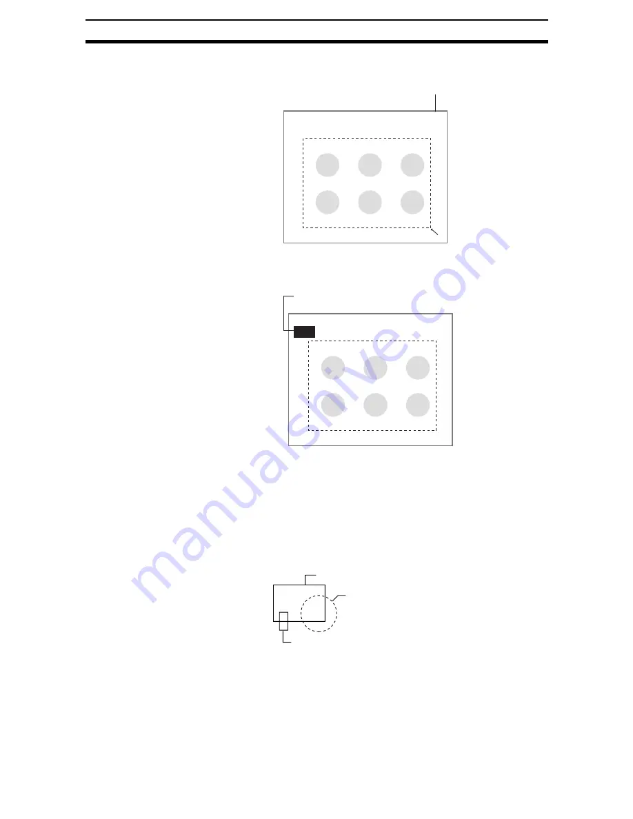
Figures drawn in OR mode are displayed in solid lines. Figures drawn in
NOT mode are displayed in dotted lines.
Inspected region
492,405
[0]
Up to three figures (0, 1, and 2)
can be drawn.
Inspected region
Add
Figure0
End
Once three figures have been drawn,
Add will no longer be displayed.
Figure 1 (drawn using OR)
Figure 2 (drawn using NOT)
Figure 3 (drawn using OR)