Appendix
Parameters (function codes) and instruction codes under different control methods
FR-A800
A - 5
A.3
Parameters (function codes) and instruction codes under
different control methods
Instruction codes are used to read and write parameters in accordance with the Mitsubishi inverter
protocol of RS-485 communication.
(For RS-485 communication, refer to page 5-610.)
Function availability under each control method is shown as below:
: Available
×: Not available
Δ: Available only during position control set by parameter
If function availability differs between using induction motors with an encoder and using PM
motors with a resolver, the function availability using PM motors with a resolver is described in
parentheses. Also, a PM motor with a resolver is not available under the torque control.
#
For "parameter copy", "parameter clear", and "all parameter clear", "
" indicates the function is
available, and "×" indicates the function is not available.
,
These parameters are not cleared by the parameter clear (all parameter clear) command, which
are sent through RS-485 communication. (For RS-485 communication, refer to page 5-610.)
$
When a communication option is installed, parameter clear (lock release) during password lock
(Pr. 297
≠
"9999") can be performed only from the communication option.
%
Available when the IPM motor MM-CF series is used and the low-speed range high-torque char-
acteristic is enabled (Pr. 788 = "9999 (initial value)").
&
Reading and writing via the PU connector are available.
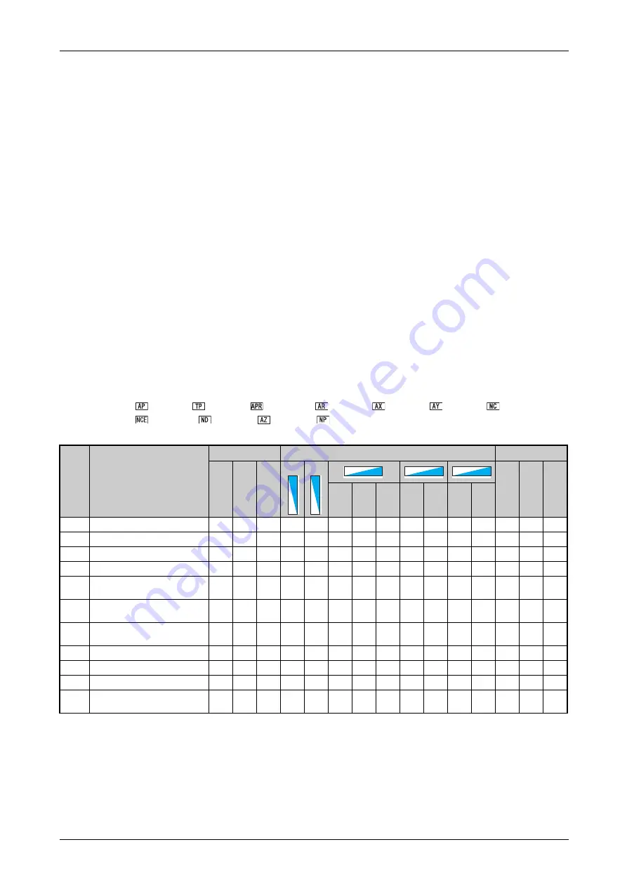
Symbols in the table indicate parameters that operate when the options are connected.
FR-A8AP,
FR-A8TP,
FR-A8APR, FR-A8AR, FR-A8AX, FR-A8AY, FR-A8NC,
FR-A8NCE, FR-A8ND, FR-A8AZ,
FR-A8NP
Pr.
Name
Instruction code
Parameter
Read
Wr
it
e
Ex
tende
d
Co
py
Clear
All
cl
ea
r
Sp
ped
co
nt
rol
To
rq
u
e
co
nt
rol
Po
si
ti
o
n
co
nt
rol
Sp
ped
co
nt
rol
To
rq
u
e
co
nt
rol
Sp
ped
co
nt
rol
Po
si
ti
o
n
co
nt
rol
0
Torque boost
00
80
0
x
x
x
x
x
x
x
x
1
Maximum frequency
01
81
0
2
Minimum frequency
02
82
0
x
x
3
Base frequency
03
83
0
x
x
x
x
x
x
x
x
4
Multi-speed setting
(high speed)
04
84
0
Δ
Δ
5
Multi-speed setting
(middle speed)
05
85
0
Δ
Δ
6
Multi-speed setting
(low speed)
06
86
0
Δ
Δ
7
Acceleration time
07
87
0
Δ
Δ
8
Deceleration time
08
88
0
Δ
Δ
9
Electronic thermal O/L relay
09
89
0
10
DC injection brake operation
frequency
0A
8A
0
x
x
Tab. A-3:
Parameter list with instruction codes (1)
V/FV/FV/F
Magnetic fluxMagnetic fluxMagnetic flux
Vector
Vector
Vector
Sensorless
Sensorless
Sensorless
PM
PM
PM
Summary of Contents for FR-A800
Page 2: ......
Page 4: ......
Page 22: ...Contents XVIII ...
Page 30: ...Related manuals Introduction 1 8 ...
Page 122: ...Connection of stand alone option units Installation and wiring 2 92 ...
Page 180: ...Basic operation procedure JOG operation Basic operation 4 32 ...
Page 934: ...Check first when you have a trouble Protective functions 6 46 ...
Page 1031: ...Appendix EC Declarations of Conformity FR A800 A 47 ...
Page 1032: ...EC Declarations of Conformity Appendix A 48 ...
Page 1033: ...Appendix EC Declarations of Conformity FR A800 A 49 ...
Page 1034: ...EC Declarations of Conformity Appendix A 50 ...
Page 1035: ...Appendix EC Declarations of Conformity FR A800 A 51 A 5 2 EMC Directive ...
Page 1036: ...EC Declarations of Conformity Appendix A 52 ...
Page 1037: ...Appendix EC Declarations of Conformity FR A800 A 53 ...
Page 1038: ...EC Declarations of Conformity Appendix A 54 ...
Page 1039: ...Appendix EC Declarations of Conformity FR A800 A 55 ...
Page 1040: ...EC Declarations of Conformity Appendix A 56 ...
Page 1041: ......


