Position control under vector control and PM sensorless vector control
Parameters
5 - 150
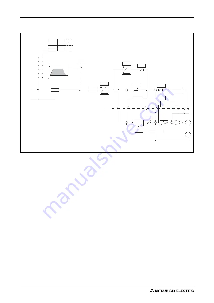
Control block diagram
Operation example
●
Calculate the speed command so that the difference between the number of pulses of the internal
pulse train (if Pr. 419 = "0", command pulses are used in the inverter from the number of pulses
defined by parameters (Pr. 465 to Pr. 494)) and the number of pulses in the feedback from the
motor terminal encoder (estimated value when PM sensorless vector control is used) is 0, and then
rotate the motor based on the calculation.
–
Once a pulse train is input, pulses are accumulated in the deviation counter, and the droop
pulses in this counter become position control pulses and speed command.
–
When the motor starts to rotate in response to the speed command from the inverter, feedback
pulses are also generated by the encoder at the same time. Subtract the encoder feedback
pulses or feedback estimate value from the droop pulses in the deviation counter. The
deviation counter keeps rotating the motor while keeping a certain droop amount.
–
If the command pulse input stops, the amount of droop pulses in the deviation counter
decreases and thus the speed slows down. When there is no droop pulse, the motor stops.
–
If the number of droop pulses becomes smaller than the value set in Pr. 426 "In-position width",
the system determines that positioning is complete and the positioning completion signal
(Y36) is turned ON.
I002535E
Fig. 5-57:
Control block diagram
0
M
2
0,1
+
+
+
+
+
+
-
-
-
-
+
0,1
2
2
2
1
0
0
JOG
NP
RH
RM
RL
REX
STF
STR
Point table
Position Speed
Acceleration/deceleration time
Position command
source selection
Pr. 419
Multi-speed,
communication
Travel
distance
Pr. 4 to 6, Pr. 24 to Pr. 27,
Pr. 232 to Pr. 239
Pr. 465 to Pr. 494
Pr. 1222 to Pr. 1281
Command pulse selection
Pr. 428
Pr. 420
Pr. 421
Electronic
gear
Pr. 424
Position command
acceleration/deceleration
time constant
Pr. 877
Command pulse
Pulse train sign
Position feed
forward
command filter Position feed
forward gain
Pr. 425
Pr. 423
Model position
control gain
Pr. 446
integral
integral
J
Torque coefficient
Pr. 828
Model speed
control gain
Speed feed
forward gain
Position
control gain
Deviation
counter
Speed control
Pr. 422
Pr. 429
Clear signal
selection
Differentiation
Torque
control
Encoder
Position feedback
(estimated value under PM sensorless vector control)
Summary of Contents for FR-A800
Page 2: ......
Page 4: ......
Page 22: ...Contents XVIII ...
Page 30: ...Related manuals Introduction 1 8 ...
Page 122: ...Connection of stand alone option units Installation and wiring 2 92 ...
Page 180: ...Basic operation procedure JOG operation Basic operation 4 32 ...
Page 934: ...Check first when you have a trouble Protective functions 6 46 ...
Page 1031: ...Appendix EC Declarations of Conformity FR A800 A 47 ...
Page 1032: ...EC Declarations of Conformity Appendix A 48 ...
Page 1033: ...Appendix EC Declarations of Conformity FR A800 A 49 ...
Page 1034: ...EC Declarations of Conformity Appendix A 50 ...
Page 1035: ...Appendix EC Declarations of Conformity FR A800 A 51 A 5 2 EMC Directive ...
Page 1036: ...EC Declarations of Conformity Appendix A 52 ...
Page 1037: ...Appendix EC Declarations of Conformity FR A800 A 53 ...
Page 1038: ...EC Declarations of Conformity Appendix A 54 ...
Page 1039: ...Appendix EC Declarations of Conformity FR A800 A 55 ...
Page 1040: ...EC Declarations of Conformity Appendix A 56 ...
Page 1041: ......


