Rev. 1.0, 02/00, page v of 19
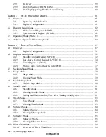
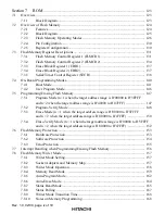
7.9
Notes when Converting the F–ZTAT Application Software to the Mask-ROM
Versions ............................................................................................................................ 169
Section 8
RAM
.................................................................................................................. 171
8.1
Overview........................................................................................................................... 171
8.1.1
Block Diagram.................................................................................................. 171
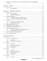
Section 9
Clock Pulse Generator
.................................................................................. 173
9.1
Overview........................................................................................................................... 173
9.1.1
Block Diagram.................................................................................................. 173
9.1.2
Register Configuration...................................................................................... 173
9.2
Register Descriptions ........................................................................................................ 174
9.2.1
Standby Control Register (SBYCR) ................................................................. 174
9.2.2
Low-Power Control Register (LPWRCR) ........................................................ 175
9.3
Oscillator........................................................................................................................... 176
9.3.1
Connecting a Crystal Resonator ....................................................................... 176
9.3.2
External Clock Input......................................................................................... 178
9.4
Duty Adjustment Circuit................................................................................................... 181
9.5
Medium-Speed Clock Divider .......................................................................................... 181
9.6
Bus Master Clock Selection Circuit .................................................................................. 181
9.7
Subclock Oscillator Circuit ............................................................................................... 182
9.7.1
Connecting 32.768 kHz Crystal Resonator....................................................... 182
9.7.2
When Subclock is not Needed .......................................................................... 183
9.8
Subclock Waveform Shaping Circuit................................................................................ 183
9.9
Notes on the Resonator ..................................................................................................... 183
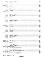
Section 10 I/O Port
.............................................................................................................. 185
10.1
Overview........................................................................................................................... 185
10.1.1
Port Functions................................................................................................... 185
10.1.2
Port Input .......................................................................................................... 185
10.1.3
MOS Pull-Up Transistors ................................................................................. 188
10.2
Port 0................................................................................................................................. 189
10.2.1
Overview .......................................................................................................... 189
10.2.2
Register Configuration...................................................................................... 190
10.2.3
Pin Functions .................................................................................................... 191
10.2.4
Pin States .......................................................................................................... 191
10.3
Port 1................................................................................................................................. 192
10.3.1
Overview .......................................................................................................... 192
10.3.2
Register Configuration...................................................................................... 192
10.3.3
Pin Functions .................................................................................................... 196
10.3.4
Pin States .......................................................................................................... 197
10.4
Port 2................................................................................................................................. 198
10.4.1
Overview .......................................................................................................... 198

