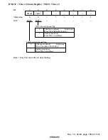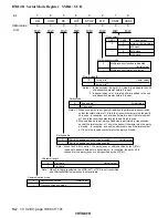
Rev. 1.0, 02/00, page 1047 of 1141
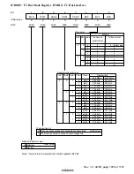
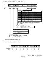
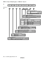
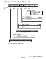
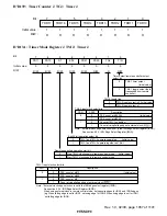
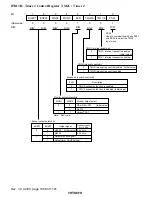
H'D119: Timer R Mode Register 2 TMRM2: Timer R
0
0
1
0
R/(W)*
2
0
R/W
3
0
4
0
R/W
5
0
6
0
7
R/(W)*
R/W
R/W
PS10
R/W
PS11
0
R/W
LAT
PS31
PS30
CP/SLM
CAPF
SLW
TMRU-1 clock source select bits
Description
0
0
Count at CFG rising edge
(Initial value)
PS10
PS11
1
PSS, count at
φ
/4
0
1
PSS, count at
φ
/256
1
PSS, count at
φ
/512
TMRU-3 clock source select bits
Description
0
0
Count at rising edge of DVCTL from frequency divider
(Initial value)
PS30
PS31
1
PSS, count at
φ
/4096
0
1
PSS, count at
φ
/2048
1
PSS, count at
φ
/1024
Interrupt select bit
Interrupt request by TMRU-2 capture signal is enabled
(Initial value)
Interrupt request by slow tracking mono-multi end is enabled
0
1
Capture signal flag
[Clearing conditions]
(Initial value)
When 0 is written after reading 1
[Setting conditions]
When TMRU-2 capture signal is generated while CP/SLM bit = 0
0
1
Slow tracking mono-multi flag
[Clearing conditions]
(Initial value)
When 0 is written after reading 1
[Setting conditions]
When slow tracking mono-multi ends while
CP/SLM bit = 1
0
1
TMRU-2 captrue signal select bits
*
0
Capture at TMRU-3 underflow
(Initial value)
CPS
LAT
0
1
Capture at CFG rising edge
1
Capture at IRQ3 edge
Description
Note: * Don't care.
Initial value :
Bit
R/W
:
:
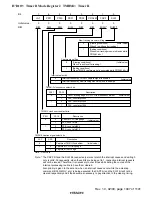
Note: * The CAPF bit and the SLW bit, respectively, works to latch the interrupt causes and writing 0
only is valid. Consequently, when these bits are being set to 1, respective interrupt requests
will not be issued. Therefore, it is necessary to check these bits during the course of the
interrupt processing routine to have them cleared.
Also priority is given to the set and, when an interrupt cause occur while the a clearing
command (BCLR, MOV, etc.) is being executed, the CAPF bit and the SLW bit will not be
cleared respectively and it thus becomes necessary to pay attention to the clearing timing.

