Rev. 1.0, 02/00, page 420 of 1141
22.2.9
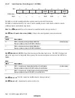
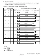
Serial Interface Mode Register 1 (SCMR1)
7
—
1
—
6
—
1
—
5
—
1
—
4
—
1
—
3
SDIR
0
R/W
0
SMIF
0
R/W
2
SINV
0
R/W
1
—
1
—
Bit :
Initial value :
R/W :
SCMR1 is an 8-bit readable/writable register used to select SCI functions.
SCMR1 is initialized to H'F2 by a reset, and in standby mode, watch mode, subactive mode,
subsleep mode, and module stop mode.
Bits 7 to 4
Reserved: These bits cannot be modified and are always read as 1.
Bit 3
Data Transfer Direction (SDIR): Selects the serial/parallel conversion format.
Bit 3
SDIR
Description
0
TDR contents are transmitted LSB-first
(Initial value)
Receive data is stored in RDR1 LSB-first
1
TDR contents are transmitted MSB-first
Receive data is stored in RDR1 MSB-first
Bit 2
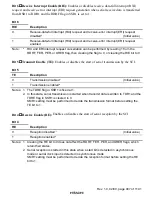
Data Invert (SINV): Specifies inversion of the data logic level. The SINV bit does not
affect the logic level of the parity bit(s): parity bit inversion requires inversion of the O/
(
bit in
SMR1.
Bit 2
SINV
Description
0
TDR1 contents are transmitted without modification
(Initial value)
Receive data is stored in RDR1 without modification
1
TDR1 contents are inverted before being transmitted
Receive data is stored in RDR1 in inverted form
Bit 1
Reserved: This bit cannot be modified and is always read as 1.
Bit 0
Reserved: 1 should not be written in this bit.


