Rev. 1.0, 02/00, page 493 of 1141
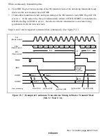
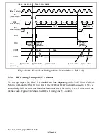
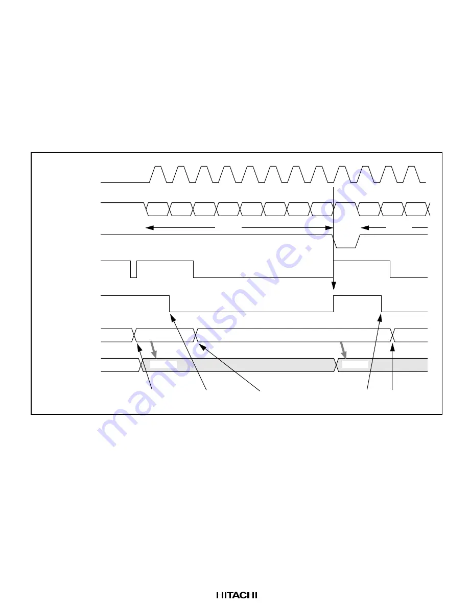
When continuously transmitting data,
6. Clear IRIC flag to 0 before startup of the 9th transmit clock of the data being transmitted, and
then write the next transmit data in ICDR.
7. 1 frame data transmission ends, and upon startup of the 9th transmit clock, IRIC flag in ICCR
is set to 1. At the same time, the next transmit data written in ICDR (ICDRT) is transferred to
ICDRS, the flag in TDRE is set to 1, then the next frame transmission is executed, being
synchronized with the internal clock.
Steps 6 and 7 can be repeated to transmit data continuously. (See figure 23.7.)
SDA
(Master output)
SDA
(Slave output)
2
1
2
3
1
4
3
6
5
8
7
9
Bit 7
Bit 6
Bit 5
Bit 7
Bit 6
Bit 5
Bit 4
Bit 3
Bit 2
Bit 1
Bit 0
IRIC
ICDRT
ICDRS
TDRE
SCL
(Master output)
Interrupt
request
generated
Data 2
Data 1
[6] Write ICDR
Write ICDR
[6] Write ICDR
[6] Clear IRIC
[6] Clear IRIC
User processing
Data 1
Data 1
Data 2
Data 3
Data 2
[7]
[7]
A
Figure 23.7 Example of Continuous Transmission Timing in Master Transmit Mode
(MLS = WAIT = 0)


