Rev. 1.0, 02/00, page 849 of 1141
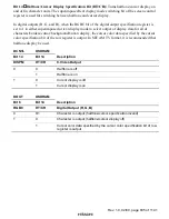
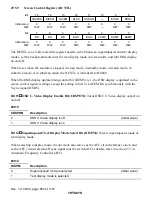
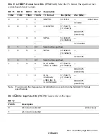
Bits 15 to 12
Reserved: Cannot be modified and are always read as 1.
Bits 11 to 9
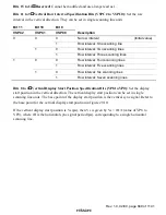
Vertical Row Interval Specification Bits (VSPC2 to VSPC0): Set the row
interval in the vertical direction. They can be set in single scanning line units.
Bit 11
Bit 10
Bit 9
VSPC2
VSPC1
VSPC0
Description
0
No row interval
(Initial value)
0
1
Row interval: One scanning line
0
Row interval: Two scanning lines
0
1
1
Row interval: Three scanning lines
0
Row interval: Four scanning lines
0
1
Row interval: Five scanning lines
0
Row interval: Six scanning lines
1
1
1
Row interval: Seven scanning lines
Bits 8 to 0
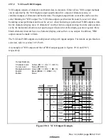
Vertical Display Start Position Specification Bits (VP8 to VP0): Set the display
start position in the vertical direction. The vertical display start position can be set in single
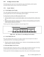
scanning line units. The base point of the display start position is the vertical sync signal. Refer to
the base point for the vertical display start position in figure 29.10.
If the vertical display start position is Vs (
µ
s), then Vs is given by Vs = tH
×
(value of VP8 to
VP0), where tH is the horizontal sync signal period (
µ
s), corresponding to a single horizontal
scanning line.

