Rev. 1.0, 02/00, page 613 of 1141
26.4.8
Cautions
•
When both the 5-bit DFG counter and 16-bit timer counter are operating, the latter is not
cleared if input of DPG and DFG signals is stopped. This leads to free-running of the 16-bit
timer counter, and periodical detection of matching by the 16-bit timer counter. In such a case,
the period of the output from the HSW timing generator is independent from DPG or DFG.
•
Specify the mode setting bit (LOP) of the HSW mode register 2 (HSM2) immediately before
writing the FIFO data.
•
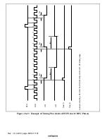
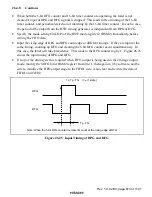
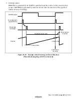
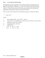
Input the rising edge of DPG and DFG count edge at different timings. If they are input at the
same timing, counting up DFG and clearing the 5-bit DFG counter occur simultaneously. In
this case, the latter will take precedence. This leads to the DFG counter lag by 1. Figure 26.25
shows the input timing of DPG and DFG.
•
If stop of the drum system is required when FIFO output is being used in the 20-stage output
mode, modify the SOFG bit of HSM2 register from 0 to 1, then again to 0 by software, and be
sure to initialize the FIFO output stage to the FIFO1 side. Also clear and rewrite the data of
FIFO1 and FIFO2.
DPG
I ± Tp · FG | >
φ
(1 state)
Tp · FG
DFG
Note: When the 5-bit DFG counter increments count at the rising edge of DFG
Figure 26.25 Input Timing of DPG and DFG

