Rev. 1.0, 02/00, page 561 of 1141
26.2.4
Register Configuration
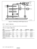
Table 26.3 shows the register configuration of the servo port section.
Table 26.3
Register Configuration
Name
Abbrev.
R/W
Size
Initial Value
Address
Servo port mode register
SPMR
R/W
Byte
H'5F
H'D0A0
Servo monitor control register
SVMCR
R/W
Byte
H'C0
H'D0A3
CTL gain control register
CTLGR
R/W
Byte
H'C0
H'D0A4
26.2.5
Register Description
Servo Port Mode Register (SPMR)
0
1
1
1
2
1
3
1
4
1
0
R/W
5
6
7
0
R/W
CTLSTOP
CFGCOMP
1
Bit :
Initial value :
R/W :
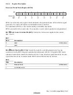
SPMR is an 8-bit read/write register that switches the CFG input system.
It is initialized to H'5F by a reset or in stand-by mode.
Bit 7
CTLSTOP Bit (CTLSTOP) : Controls whether the CTL circuit is operated or stopped.
Bit 7
CTLSTOP
Description
0
CTL circuit operates
(Initial value)
1
CTL circuit stops operation
Bit 6
Reserved: Cannot be modified and is always read as 1.
Bit 5
CFG Input System Switching Bit (CFGCOMP) : Selects whether the CFG input signal
system is set to the zero cross type comparator system or digital signal input system.
Bit 5
CFGCOMP
Description
0
CFG signal input system is set to the zero cross type comparator system.
(Initial value)
1
CFG signal input system is set to the digital signal input system.
Bits 4 to 0
Reserved: Cannot be modified and are always read as 1.


