Rev. 1.0, 02/00, page 699 of 1141
•
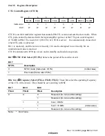
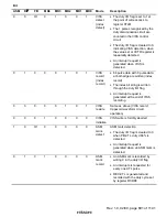
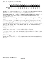
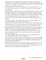
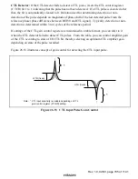
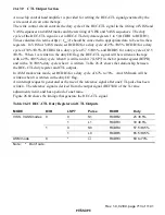
VISS Detect Mode and VASS Detect Mode: The duty I/O flag indicates the result of duty
discrimination. The duty I/O flag is 1 when the duty cycle of the PB-CTL signal is above 44%
(a 0 pulse in the CTL signal). The duty I/O flag is 0 when the duty cycle of the PB-CTL signal
is below 44% (a 1 pulse in the CTL signal).
•
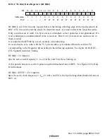
ASM Mark Detect Mode: The duty I/O flag indicates the result of duty discrimination. The
duty I/O flag is 0 when the duty cycle of the PB-CTL signal is above 66% (when an ASM
mark is detected).
•
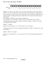
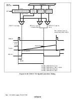
VISS Record Mode and VISS Rewrite Mode: The duty I/O flag operates according to a control
signal from the VISS control circuit, and controls the write control circuit so as to write an
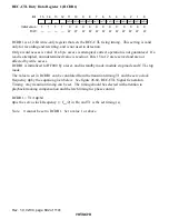
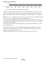
index code. The write timing is set in the REC-CTL duty data registers (RCDR1 to RCDR5).
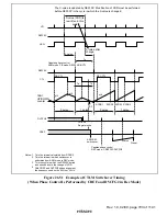
For VISS recording, registers RCDR1 to RCDR5 are set with reference to REF30X. For VISS
rewrite, RCDR2 to RCDR5 are set with reference to the low-to-high transition of the
previously recorded CTL signal, and the write is carried out through the trapezoid waveform
generator.
Set the duty timing for a 1 pulse (short) in RCDR2, for a 1 pulse (long) in RCDR3, for a 0
pulse (short) in RCDR4, and for a 0 pulse (long) in RCDR5.
While an index code is being written, the value of the bit being written can be read by reading
the duty I/O flag. If the CTL signal currently being written is a 0 pulse, the duty I/O flag will
read 1. If the CTL signal currently being written is a 1 pulse, the duty I/O flag will read 0.
•
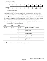
VASS Record Mode and VASS Rewrite Mode: The duty I/O flag is used for write control, one
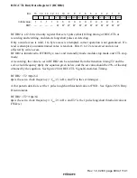
CTL pulse at a time. The write timing is set in the REC-CTL duty data registers (RCDR1 to
RCDR5). For VASS recording, registers RCDR1 to RCDR5 are set with reference to
REF30X. For VASS rewrite, RCDR2 to RCDR5 are set with reference to the low-to-high
transition of the previously recorded CTL signal, and the write is carried out through the
trapezoid waveform generator.
Set the duty timing for a 1 pulse (short) in RCDR2, for a 1 pulse (long) in RCDR3, for a 0
pulse (short) in RCDR4, and for 0 pulse (long) in RCDR5.
If 0 is written in the duty I/O flag, a CTL pulse will be written with a duty cycle set in RCDR2
and RCDR3, referenced to the immediately following REF30X. If 1 is written in the duty I/O
flag, a CTL pulse will be written with a duty cycle set in RCDR4 and RCDR5, referenced to
the immediately following REF30X.
•
ASM Record Mode: The duty I/O flag is used for write control, one CTL pulse at a time. The
write timing is set in the REC-CTL duty data registers (RCDR1 and RCDR3). If 0 is written
in the duty I/O flag, a CTL pulse will be written with a duty cycle of 67% to 70% as set in
RCDR3, referenced to the immediately following REF30X.


