Rev. 1.0, 02/00, page 774 of 1141
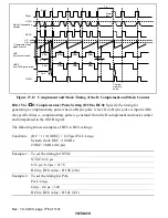
The following shows an example of VVTHR settings.
Condition:
(VVTHR – 1)
×
(2/OSC) > (Hsync period / 2 – 4.7
µ
s)
×
1.5 = 41
µ
s
System clock OSC = 10 MHz
2/OSC = 5 MHz = 0.2
µ
s
Example 1: To detect 41-
µ
s pulses
Vsync detection threshold value: 41
µ
s
41
µ
s / 0.2
µ
s = 205
HVTHR value = H'CE (206)
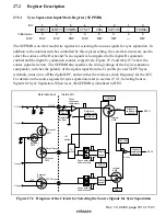
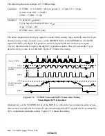
The noise component of the Csync signal in a weak field is usually large, and will cause the Vsync
detection delay or miss. In such a case, set the DLPFON (bit 2) of the SEPIMR to 1; the SEPH
signal detected by the digital H separation counter is logically ORed with the Csync signal
(Vsync), then the result is input to the digital V separation counter. This will prevent the Vsync
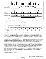
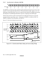
detection delay or miss in a weak field. Figure 27.9 shows this timing.
Csync + SEPH
HVTH
SEPH
SEPV
VVTH
Digital H separation
counter
Digital V separation
counter
Figure 27.9 VVTHR Value and SEPV Generation Timing
When Digital LPF Is Enabled
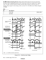
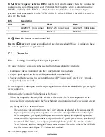
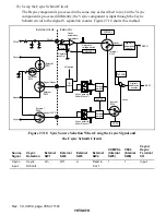
Alternatively, set the VCMPON (bit 4) of the SEPCR to 1 when the Vsync detection delay or miss
may occur in a weak field; the external Vsync detection signal (AFCV signal) will be generated by
the V complement and mask counter. Figure 27.10 shows this timing.

