Rev. 1.0, 02/00, page 675 of 1141
•
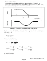
Frequency Characteristics
The computation circuit repeats computation of the function, which is obtained by s-z
conversion according to bi-linear approximation of the transfer function on the s-plane. Figure
26.41 shows the frequency characteristics of the lag-lead filter.
f1
0
f2
Frequency (Hz)
20log(f1/f2)
gain(dB)
phase(deg)
Figure 26.41 Frequency Characteristics of the Lag-Lead Filter
The pulse transfer function G (Z) is obtained by the bi-linear approximation of the transfer G (S).
In the transfer G (S),
S =
·
2
Ts
1–Z
–1
1+Z
–1
Where, assumed that Z
-1
=
e
-j
ω
Ts
,
G (Z) = G
·
·
2
Ts
1+AZ
–1
1+BZ
–1
G (Z) =
Ts +
1
f
2
Ts +
1
f
1
A =
Ts –
1
f
2
Ts +
1
f
2
B =
Ts –
1
f
1
Ts +
1
f
1
Ts: Sampling cycle (sec)

