Rev. 1.0, 02/00, page 536 of 1141
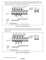
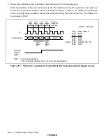
2. Figure 25.3 shows the operation when the instruction immediately preceding the trap address
is that of 2 states or more of the execution cycle and the next instruction prefetch occurs in the
second state from the last. The address to be stacked is 0268.
φ
Address bus
Interrupt
request
signal
MOV
execution
NOP
execution
Start of exception
handling
Immediately
preceding
instruction
Address
0266 MOV.B
R2L, @0000
0268 NOP
026A NOP
026C NOP
*
0266
026A
0268 0000
026C
Data
read
→
MOV
instruc-
tion
pre-fetch
NOP
instruc-
tion
pre-fetch
NOP
instruc-
tion
pre-fetch
Note:
*
Trap setting address
The underlines address is the one to be actually stacked.
Figure 25.3 Basic Operations (2)
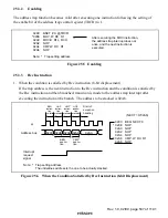
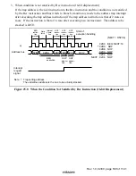
3. Figure 25.4 shows the operation when the instruction immediately preceding the trap address
is that of 1 state or 2 states or more and the prefetch occurs in the last state. The address to be
stacked is 025C.
φ
Address bus
Interrupt
request
signal
NOP
execu-
tion
NOP
execu-
tion
NOP
execu-
tion
Start of
exception
handling
Immediately
preceding
instruction
Address
0256 NOP
0258 NOP
025A NOP
025C NOP
025E NOP
*
0256
025C
0258 025A
025E
→
NOP
instruc-
tion
pre-fetch
NOP
instruc-
tion
pre-fetch
NOP
instruc-
tion
pre-fetch
NOP
instruc-
tion
pre-fetch
Note:
*
Trap setting address
The underlines address is the one to be actually stacked.
Figure 25.4 Basic Operations (3)

