Rev. 1.0, 02/00, page 760 of 1141
27.1.3
Pin Configuration
Table 27.1 shows the pin configuration of the sync separator.
Table 27.1
Sync Separator Pin Configuration
Name
Abbrev.
I/O
Function
Sync signal
input/output
Csync/Hsync
Input/output
Composite sync signal input/output or
horizontal sync signal input
VLPF/Vsync
Input
Pin for connecting external LPF for
vertical sync signal or input pin for
vertical sync signal
AFCosc
Input/output
AFC oscillation signal
AFC oscillation
signals
AFCpc
Input/output
AFC by-pass capacitor connecting pin
LPF for AFC
AFCLPF
Input/output
External LPF connecting pin for AFC
Composite video
signal
CVin2
Input
Composite video signal input (2 Vpp,
with a sync tip clamp circuit)
27.1.4
Register Configuration
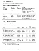
Table 27.2 shows the sync separator registers.
Table 27.2
Sync Separator Registers
Name
Abbrev.
R/W
Size
Initial
Value
Address
*
1
Sync separation input mode register
SEPIMR
R/W
Byte
H'00
H'D240
Sync separation control register
SEPCR
R/(W)
*
2
Byte
H'00
H'D241
Sync separation AFC control register
SEPACR
R/(W)
*
2
Byte
H'10
H'D242
Horizontal sync signal threshold register
HVTHR
W
Byte
H'E0
H'D243
Vertical sync signal threshold register
VVTHR
W
Byte
H'00
H'D244
Field detection window register
FWIDR
W
Byte
H'F0
H'D245
H complement and mask register
HCMMR
W
Word
H'0000
H'D246
Noise detection counter
NDETC
R
Byte
H'00
H'D248
Noise detection level register
NDETR
W
Byte
H'00
H'D248
Data slicer detection window register
DDETWR
W
Byte
H'00
H'D249
Internal sync signal frequency register
INFRQR
W
Byte
H'10
H'D24A
Notes: 1. Lower 16 bits of the address.
2. Only 0 can be written to clear the flag.


