Rev. 1.0, 02/00, page 623 of 1141
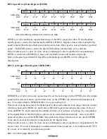
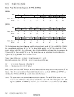
DFG Lock LOWER Data Register (DFRLDR)
8
0
9
0
W
10
0
W
11
0
12
0
W
0
W
13
14
0
15
DFRLDR12 DFRLDR11 DFRLDR10 DFRLDR9 DFRLDR8
1
W
DFRLDR15
W
W
W
DFRLDR14 DFRLDR13
Bit :
Initial value :
R/W :
0
0
1
0
W
2
0
W
3
0
4
0
W
0
W
5
6
0
7
DFRLDR4 DFRLDR3 DFRLDR2 DFRLDR1 DFRLDR0
0
W
DFRLDR7
W
W
W
DFRLDR6 DFRLDR5
Bit :
Initial value :
R/W :
DFRLDR is a 16-bit write-only register used to set the lock range on the LOWER side when drum
speed lock is detected, and to set the limit value on LOWER side when limiter function is in use.
Set a signed data to DFRLDR (bit 15 is a sign-setting bit).
When lock is being detected, if the drum speed is detected within the lock range, the lock counter
which has been set by DFRCS 1 and 0 bits of DFVCR register decrements the count. If the set
value of DFRCS 1 and 0 matches the number of times of occurrence of locking, the computation
of the digital filter in the drum phase system can be controlled automatically. Also, if the DFG
speed error data is under the DFRLDR value when the limiter function is in use, the DFRLDR
value can be used as the data for computation by the digital filter.
Only a word access is valid. If a byte access is attempted, correct operation is not guaranteed. No
read is valid. If a read is attempted, an undetermined value is read out. It is initialized to H'8000
by a reset, or in stand-by or module-stop mode.
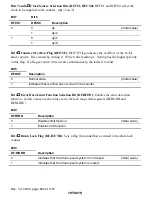
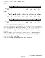
Drum Speed Error Detection Control Register (DFVCR)
0
0
1
0
(R)
*2
/W
2
0
R/W
3
0
4
0
R/W
0
R/(W)
*1
5
6
0
7
DFRFON DF-R/UNR
DPCNT
DFRCS1
DFRCS0
0
R/W
DFCS1
(R)
*2
/W
R
R/W
DFCS0
DFOVF
Notes:
Bit :
Initial value :
R/W :
1. Only 0 can be written.
2. If read-accessed, the counter value is read out.
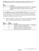
DFVCR is an 8-bit read/write register that controls the operation of drum speed error detection.
Bit 3 accepts only read, and bit 5 accepts only read and 0 write. It is initialized to H'00 by a reset,
or in stand-by or module-stop mode.

