Rev. 1.0, 02/00, page 248 of 1141
11.1.2
Block Diagram
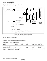
Figure 11.1 shows a block diagram of timer A.
[Legend]
TMA
32 kHz
Crystal oscillator
Overflowing of
the interval
timer
System
clock
φ
w
φ
w/128
φ
/16384,
φ
/8192,
φ
/4096,
φ
/1024,
φ
/512,
φ
/256,
φ
/64,
φ
/16
φ
TCA
: Timer mode register A
: Timer counter A
Note: * Selectable only when the prescaler W output (
φ
w/128) is
working as the input clock to the TCA.
Prescaler S
(PSS)
Interrupting
circuit
Prescaler unit
Prescaler W
(PSW)
TCA
1/4
TMA
Interrupt
requests
Internal data bus
÷
8
*
÷
64
*
÷
128
*
÷
256
*
Figure 11.1 Block Diagram of Timer A
11.1.3
Register Configuration
Table 11.1 shows the register configuration of timer A.
Table 11.1
Register Configuration
Name
Abbrev.
R/W
Size
Initial Value
Address*
Timer mode register A
TMA
R/W
Byte
H'30
H'FFBA
Timer counter A
TCA
R
Byte
H'00
H'FFBB
Note:
*
Lower 16 bits of the address.

