Rev. 1.0, 02/00, page 797 of 1141
27.3.7
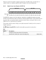
Module Stop Control Register (MSTPCR)
7
1
R/W
6
1
R/W
5
4
1
R/W
1
R/W
3
1
R/W
2
1
R/W
1
1
R/W
0
1
R/W
7
1
R/W
6
1
R/W
5
1
R/W
4
1
R/W
3
1
R/W
2
1
R/W
1
1
R/W
0
1
R/W
Bit :
Initial value :
MSTP15 MSTP14 MSTP13 MSTP12 MSTP11 MSTP10 MSTP9 MSTP8 MSTP7 MSTP6 MSTP5 MSTP4
MSTP3 MSTP2 MSTP1 MSTP0
R/W :
MSTPCRH
MSTPCRL
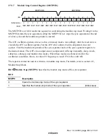
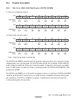
The MSTPCR is a 16-bit read/write register for controlling the module stop mode. Writing 0 to the
MSTP9 bit starts the sync separator; setting the MSTP9 bit to 1 stops the sync separator at the end
of a bus cycle and the module stop mode is entered.
The AFC oscillator operates in reset, active, and sleep modes. Accordingly, after the reset state is
cleared, the AFC oscillator operates but the AFC error output circuit (comparator) does not
operate. Clear the module stop mode of the sync separator and set the sync separator registers to
the desired values. The AFC error output circuit (comparator) will stop in standby, sleep, watch,
subactive, subsleep, and module stop modes. When these modes are cleared, wait for the
oscillation to stabilize, that is, for the AFC frequency to reach 576
×
fh or 448
×
fh.
The registers cannot be read or written to in module stop mode. For details, refer to section 4.5,
Module Stop Mode.
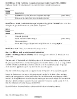
Bit 9
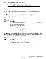
Module Stop (MSTP9): Specifies the module stop mode of the sync separator.
Bit 9
MSTP9
Description
0
Clears the module stop mode of the sync separator
1
Specifies the module stop mode of the sync separator
(Initial value)


