Rev. 1.0, 02/00, page 73 of 1141
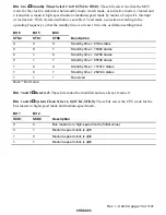
Bits 6 to 4
Standby Timer Select 2 to 0 (STS2 to STS0): These bits select the time the MCU
waits for the clock to stabilize when standby mode, watch mode, or subactive mode is cleared and
a transition is made to high-speed mode or medium-speed mode by means of a specific interrupt
or instruction. With crystal oscillation, see table 4.5 and make a selection according to the
operating frequency so that the standby time is at least 10 ms (the oscillation settling time).
Bit 6
Bit 5
Bit 4
STS2
STS1
STS0
Description
0
0
0
Standby time = 8192 states
0
0
1
Standby time = 16384 states
0
1
0
Standby time = 32768 states
0
1
1
Standby time = 65536 states
1
0
0
Standby time = 131072 states
1
0
1
Standby time = 262144 states
1
1
*
Reserved
Note:
*
Don't care
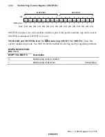
Bits 3 and 2
Reserved: These bits cannot be modified and are always read as 0.
Bits 1 and 0
System Clock Select 1, 0 (SCK1, SCK0): These bits select the CPU clock for the
bus master in high-speed mode and medium-speed mode.
Bit 1
Bit 2
SCK1
SCK0
Description
0
0
Bus master is in high-speed mode (Initial value)
0
1
Medium-speed clock is
φ
/16
1
0
Medium-speed clock is
φ
/32
1
1
Medium-speed clock is
φ
/64

