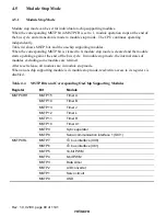
Rev. 1.0, 02/00, page 81 of 1141
4.6
Standby Mode
4.6.1
Standby Mode
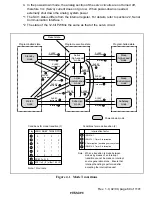
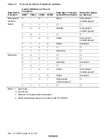
If a SLEEP instruction is executed when the SSBY bit in SBYCR is set to 1, the LSON bit in
LPWRCR is cleared to 0, and the TMA3 bit in TMA (Timer A) is cleared to 0, standby mode will
be entered. In this mode, the CPU, on-chip supporting modules, and oscillator (except for
subclock oscillator) all stop. However, the contents of the CPU's internal registers and data in the
on-chip RAM, as well as on-chip peripheral circuits (with some exceptions), are maintained in the
current state. (Timer X1 and SCI1 are partially reset.) The I/O port, at this time, is caused to the
high impedance state.
In this mode the oscillator stops, and therefore power dissipation is significantly reduced.
4.6.2
Clearing Standby Mode
Standby mode is cleared by an external interrupt (pin
,54
3
to
,54
4
), or by means of the
5(6
pin.
Clearing with an Interrupt: When an
,54
3
to
,54
4
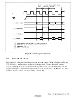
interrupt request signal is input, clock
oscillation starts, and after the elapse of the time set in bits STS2 to STS0 in SYSCR, stable clocks
are supplied to the entire chip, standby mode is cleared, and interrupt exception handling is
started.
Standby mode cannot be cleared with an
,54
3
to
,54
4
interrupt if the corresponding enable bit
has been cleared to 0 or has been masked by the CPU.
Clearing with the
5(6
5(6
5(6
5(6
Pin: When the
5(6
pin is driven low, clock oscillation is started. At the
same time as clock oscillation starts, clocks are supplied to the entire chip. Note that the
5(6
pin
must be held low until clock oscillation stabilizes. When the
5(6
pin goes high, the CPU begins
reset exception handling.
4.6.3
Setting Oscillation Settling Time after Clearing Standby Mode
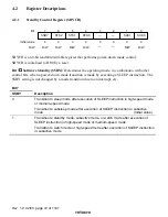
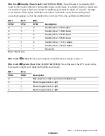
Bits STS2 to STS0 in SBYCR should be set as described below.
Using a Crystal Oscillator: Set bits STS2 to STS0 so that the standby time is at least 10 ms (the
oscillation settling time).
Table 4.5 shows the standby times for different operating frequencies and settings of bits STS2 to
STS0.


