Rev. 1.0, 02/00, page 380 of 1141
20.1.2
Block Diagram
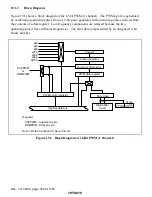
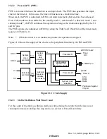
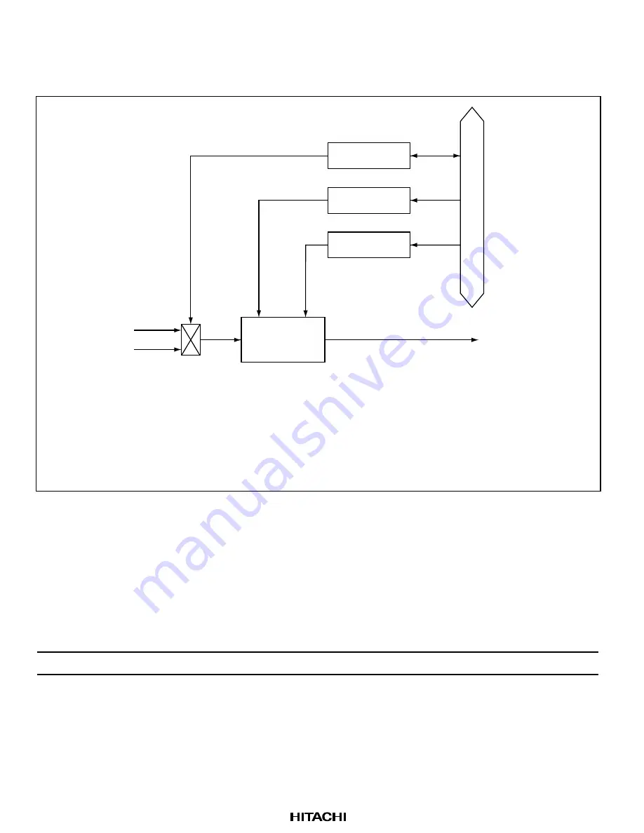
Figure 20.1 shows a block diagram of the 14-bit PWM.
[Legend]
PWCR
φ
/4
φ
/2
PWDRL
: PWM control register
: PWM data register L
PWDRU
PWM14
: PWM data register U
: PWM14 output pin
Internal data bus
PWCR
PWDRL
PWDRU
PWM waveform
generator
PWM14
Figure 20.1 Block Diagram of 14-Bit PWM
20.1.3
Pin Configuration
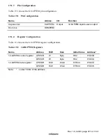
Table 20.1 shows the 14-bit PWM pin configuration.
Table 20.1
Pin Configuration
Name
Abbrev.
I/O
Function
PWM 14-bit square-wave output pin
PWM14*
Output
14-bit PWM square-wave output
Note:
*
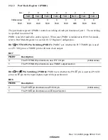
This pin also functions as P40 general I/O pin. When using this pin, set the pin function
by the port mode register 4 (PMR4). For details, see section 10.6, Port 4.

