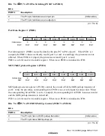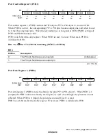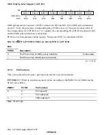
Rev. 1.0, 02/00, page 196 of 1141
10.3.3
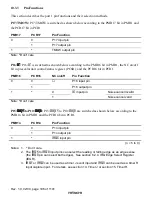
Pin Functions
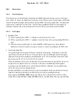
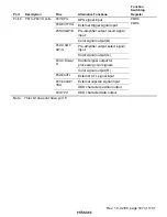
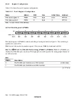
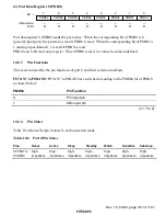
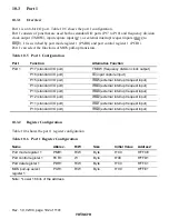
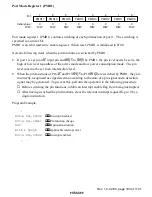
This section describes the port 1 pin functions and their selection methods.
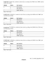
P17/TMOW: P17/TMOW is switched as shown below according to the PMR17 bit in PMR1 and
the PCR17 bit in PCR1.
PMR17
PCR17
Pin Function
0
P17 input pin
0
1
P17 output pin
1
*
TMOW output pin
Note:
*
Don’t care
P16/
,&
,&
,&
,&
: P16/
,&
is switched as shown below according to the PMR16 bit in PMR1, the NC on/off
bit in prescalar unit control/status register (PCSR), and the PCR16 bit in PCR1.
PMR16
PCR16
NC on/off
Pin Function
0
P16 input pin
0
1
P16 output pin
0
Noise cancel invalid
1
*
1
,&
input pin
Noise cancel valid
Note:
*
Don’t care
P15/
,54
8
,54
8
,54
8
,54
8
to P10/
,54
3
,54
3
,54
3
,54
3
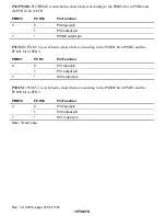
: P15/
,54
48
to P10/
,54
3
are switched as shown below according to the
PMR1n bit in PMR1 and the PCR1n bit in PCR1.
PMR1n
PCR1n
Pin Function
0
P1n input pin
0
1
P1n output pin
1
*
,54Q
input pin
(n = 5 to 0)
Notes: 1.
*
Don’t care.
2. The
,54
8
to
,54
3
input pins can select the leading or falling edge as an edge sense
(the
,54
3
pin can select both edges). See section 6.2.4, IRQ Edge Select Register
(IEGR).
3.
,54
4
or
,54
5
can be used as a timer J event input and
,54
6
can be used as a timer R
input capture input. For details, see section 13, Timer J or section 15, Timer R.


