Rev. 1.0, 02/00, page 1126 of 1141
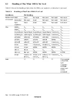
Pin States
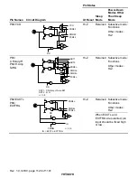
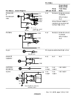
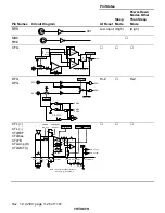
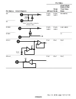
Pin Names
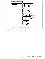
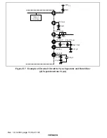
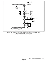
Circuit Diagram
At Reset
Sleep
Mode
Power-Down
Modes Other
Than Sleep
Mode
5(6
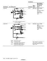
RST
Low input (High)
(High)
MD0
FWE
CFG
+
-
+
-
+
-
CFGCOMP
CFGCOMP
P250
REF
M250
S
R
F/F
O
stp
VREF
VREF
CFG
BIAS
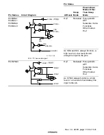
Res+ModuleSTOP
DFG
DPG
RD ·
PDRn
DFG
DPG
PMRn
PCRn
DPG SW
DPG SW
Pes+LPM
DFG
DPG
Hi-Z
Hi-Z
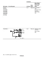
CTL (+)
CTL (
−
)
CTLREF
CTLBias
CTLFB
CTLAmp (O)
CTLSMT (I)
+
-
-
+
+ -
CTLGR3 to 1
CTLFB
CTLGR0
AMPSHORT
(REC-CTL)
AMPON
(PB-CTL)
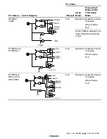
PB-CTL (+)
PB-CTL (Ð)
CTLSMT (i)
CTLREF
CTL (+)
CTL (-)
CTLBias
CTLFB CTLAmp(o)
*
Note: * Connect a capacitor between
CTLAmp (o), CTLSMT (i)

