Rev. 1.0, 02/00, page 9 of 1141
1.3.2
Pin Functions
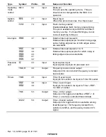
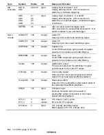
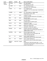
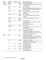
Table 1.2 summarizes the functions of the H8S/2199 Series pins.
Table 1.2
Pin Functions
Type
Symbol
Pin No.
I/O
Name and Function
V
CC
56, 112
Input
Power supply:
All Vcc pins should be connected to the system
power supply (+5V)
V
SS
57, 79,
110
Input
Ground:
All Vcc pins should be connected to the system
power supply (0V)
SV
CC
10
Input
Servo power supply:
SVcc pin should be connected to the servo
analog power supply (+5V)
SV
SS
1
Input
Servo ground:
SVss pin should be connected to the servo
analog power supply (0V)
AV
CC
36
Input
Analog power supply:
Power supply pin for A/D converter. It should be
connected to the system power supply (+5V)
when the A/D converter is not used
AV
SS
23
Input
Analog ground:
Ground pin for A/D converter. It should be
connected to the system power supply (0V)
OV
CC
18
Input
OSD power supply:
V
CC
(OSD) should be connected to the OSD
analog power supply (+5 V)
OV
SS
20
Input
OSD ground:
V
SS
(OSD) should be connected to the OSD
analog power supply (0 V)
Power
supply
V
CL
81
Input
Smoothing capacitor connection:
Connect 0.1-µF power-smoothing capacitance
between V
CL
and V
SS
OSC1
78
Input
OSC2
80
Output
Connected to a crystal oscillator. It can also
input an external clock. See section 9, Clock
Pulse Generator, for typical connection diagrams
for a crystal oscillator and external clock input
X1
76
Input
Clock
X2
75
Output
Connected to a 32.768 kHz crystal oscillator.
See section 9, Clock Pulse Generator, for typical
connection diagrams

