Rev. 1.0, 02/00, page 569 of 1141
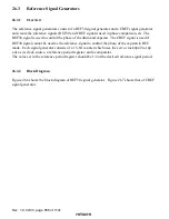
26.3.4
Register Description
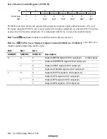
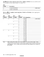
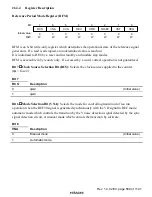
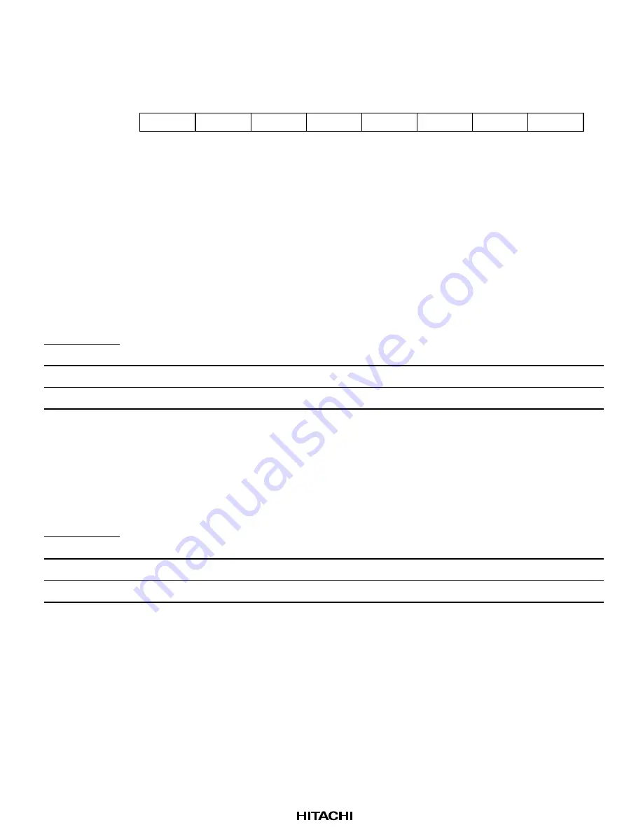
Reference Period Mode Register (RFM)
0
0
1
0
W
2
0
W
3
0
4
0
W
0
W
5
6
0
7
REX
CRD
OD/EV
VST
VEG
0
W
RCS
W
W
W
VNA
CVS
Bit :
Initial value :
R/W :
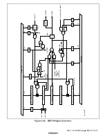
RFM is an 8-bit write-only register which determines the operational state of the reference signal
generators. If a read is attempted, an undetermined value is read out.
It is initialized to H'00 by a reset and in stand-by and module stop modes.
RFM is accessible in byte units only. If accessed by a word, correct operation is not guaranteed.
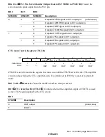
Bit 7
Clock Source Selection Bit (RCS): Selects the clock source supplied to the counter.
(
φ
s = fosc/2)
Bit 7
RCS
Description
0
φ
s/2
(Initial value)
1
φ
s/4
Bit 6
Mode Selection Bit (VNA): Selects the mode for controlling transition to free-run
operation when the REF30 signal is generated synchronously with the VD signal in REC mode:
automatic mode which controls the transition by the V noise detection signal detected by the sync
signal detection circuit, or manual mode which controls the transition by software.
Bit 6
VNA
Description
0
Manual mode
(Initial value)
1
Automatic mode

