Rev. 1.0, 02/00, page 810 of 1141
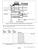
Data slicer base
point
Data sampling
clock
Start bit detection starting position
Start bit detection end position
C.video
Delay
Start
bit
Figure 28.6 Data Sampling Clock When Start Bit is not Detected
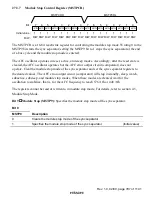
Bit 5
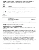
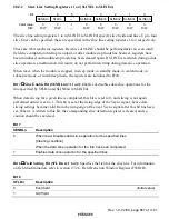
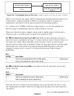
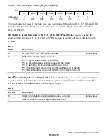
Data End Detection Flag (ENDFn n=1 to 4): Shows whether or not slice data is input at
the 18th sampling clock pulse. This flag is set when the slice data is 0, that is, when data slicing is
regarded as having been completed normally.
Bit 5
ENDFn
Description
0
Data end not detected for line for data slicing
(Initial value)
1
Data end detected for line for data slicing
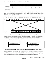
Bit 4
Reserved: Cannot be modified and is always read as 1.
Bits 3 to 0
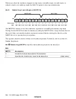
Clock Run-in Count Value (CRICn3 to CRICn0): Count result for run-in pulses
during the clock run-in period. When 16 or more pulses are input, further input pulses are not
counted in order to prevent erroneous detection, and an overflow state is maintained. Further, the
clock run-in detection window signal indicating the clock run-in period can be adjusted using the
DDETWR register of the sync separator. For details, refer to section 27.2.10, Data Slicer
Detection Window Register (DDETWR).

