Rev. 1.0, 02/00, page 784 of 1141
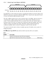
Bit 5
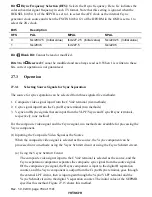
Hsync Frequency Selection (HFS): Selects the Hsync frequency. Here, fsc indicates the
color subcarrier signal frequency in each TV format. Note that this setting is ignored when the
HCKSEL bit (bit 3) of the SEPCR is set to 1 to select the AFC clock as the internal Csync
generator clock source and when the FSCIN bit (bit 12) of the DFORM in the OSD is set to 1 to
select the 2fsc clock.
Bit 5
Description
HFS
PAL
MPAL
NPAL
0
fsc/283.75 (Initial value)
fsc/227.25 (Initial value)
fsc/229.25 (Initial value)
1
fsc/283.5
fsc/227.5
fsc/229.5
Bit 4
Blank Bit: Cannot be read or modified.
Bits 3 to 0
Reserved: Cannot be modified and are always read as 0. When 1 is written to these
bits, correct operation is not guaranteed.
27.3
Operation
27.3.1
Selecting Source Signals for Sync Separation
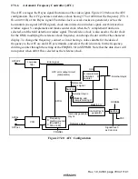
The source for sync separation can be selected from three signals (five methods):
1. Composite video signal input from the CVin2 terminal (two methods)
2. Csync signal input from the Csync/Hsync terminal (two methods)
3. Vsync and Hsync signals that are input from the VLPF/Vsync and Csync/Hsync terminals,
respectively (one method)
For the composite video signal and the Csync signal, two methods are available for processing the
Vsync component.
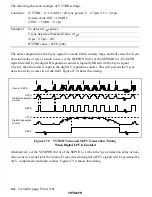
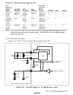
(1) Inputting the Composite Video Signal as the Source
When the composite video signal is selected as the source, the Vsync component can be
processed in two methods: using the Vsync Schmitt circuit or using the Csync Schmitt circuit.
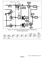
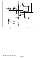
(a) Using the Vsync Schmitt Circuit
The composite video signal input to the CVin2 terminal is selected as the source, and the
Csync separation comparator separates the composite sync signal from the source signal.
Of the composite sync signal, the Hsync component is input to the digital H separation
counter, and the Vsync component is output from the Csync/Hsync terminal, goes through
the external LPF circuit, then is input again through the Vsync/VLPF terminal and the
Vsync Schmitt circuit to the digital V separation counter. The initial value of the SEPIMR
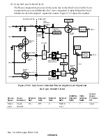
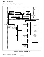
specifies this method. Figure 27.15 shows this method.


